Continued development of Mary-bot. Got the Python bot to more or less successfully run the bash script that regenerates the entire website, though the paths need to be updated for the links and the image references. Still not yet ready for full journal submission migration.
Continued development of Mary-Bot. It now can automatically name images entries. All the user needs to do is type [IMG] in the corresponding place in their text content. Not yet ready for full journal submission migration. I'd like to put in the ability to edit entries thru Discord commands as well.
Continued development of Mary-Bot. She can now track and edit the project list thru Discord commands and populate a new journal .ini automatically along with uploading a set of image files. Another day of work will be required.
Set up VPS with https and attached it to the marian-scientific.org domain. Set up the preliminaries of Mary-Bot, a Discord bot that will automatically push journal entries to the site. Another day or so of work will be required.
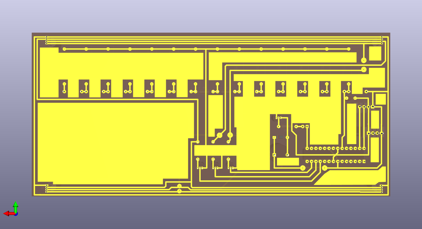
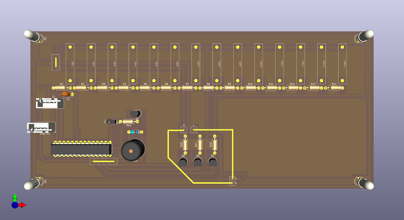
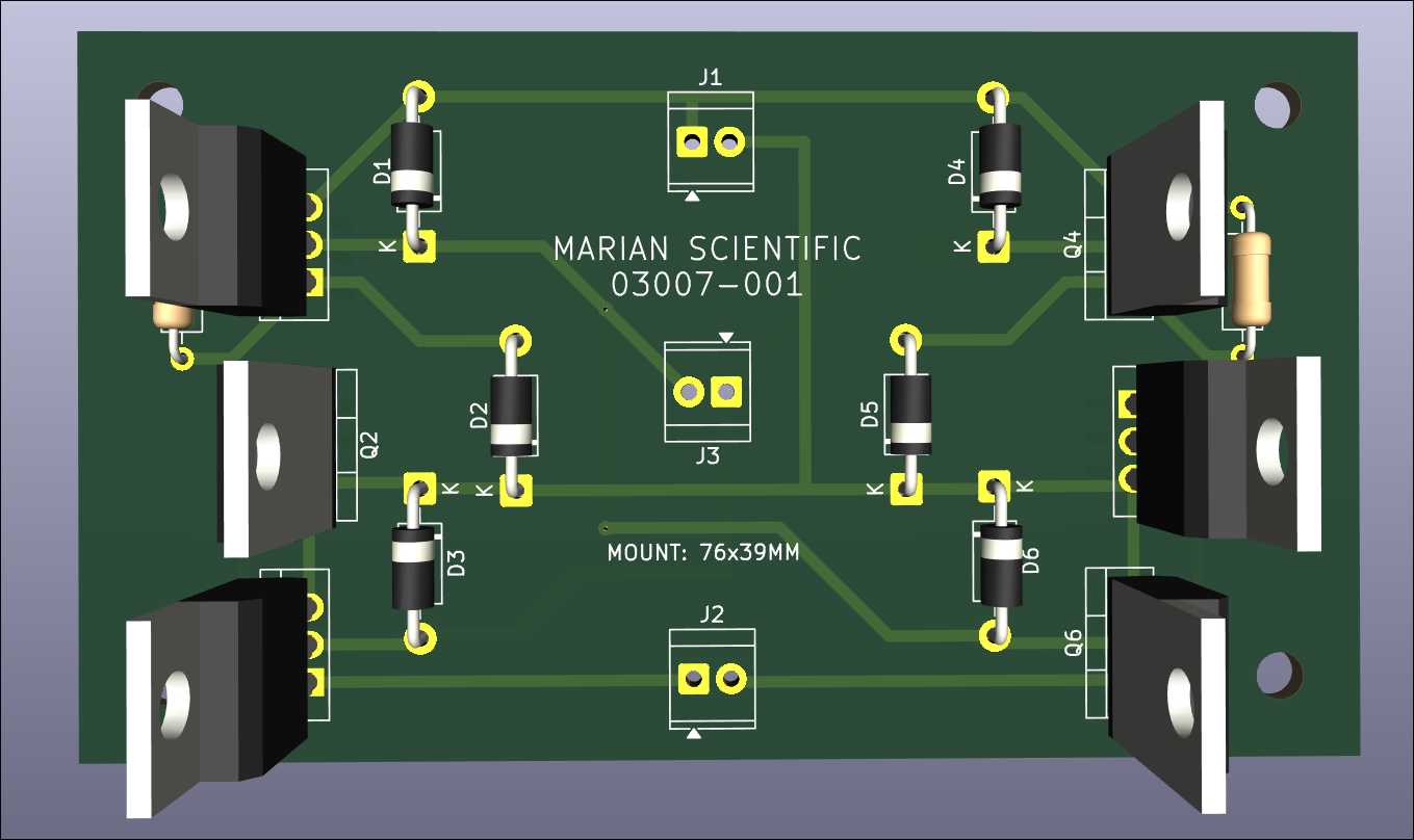
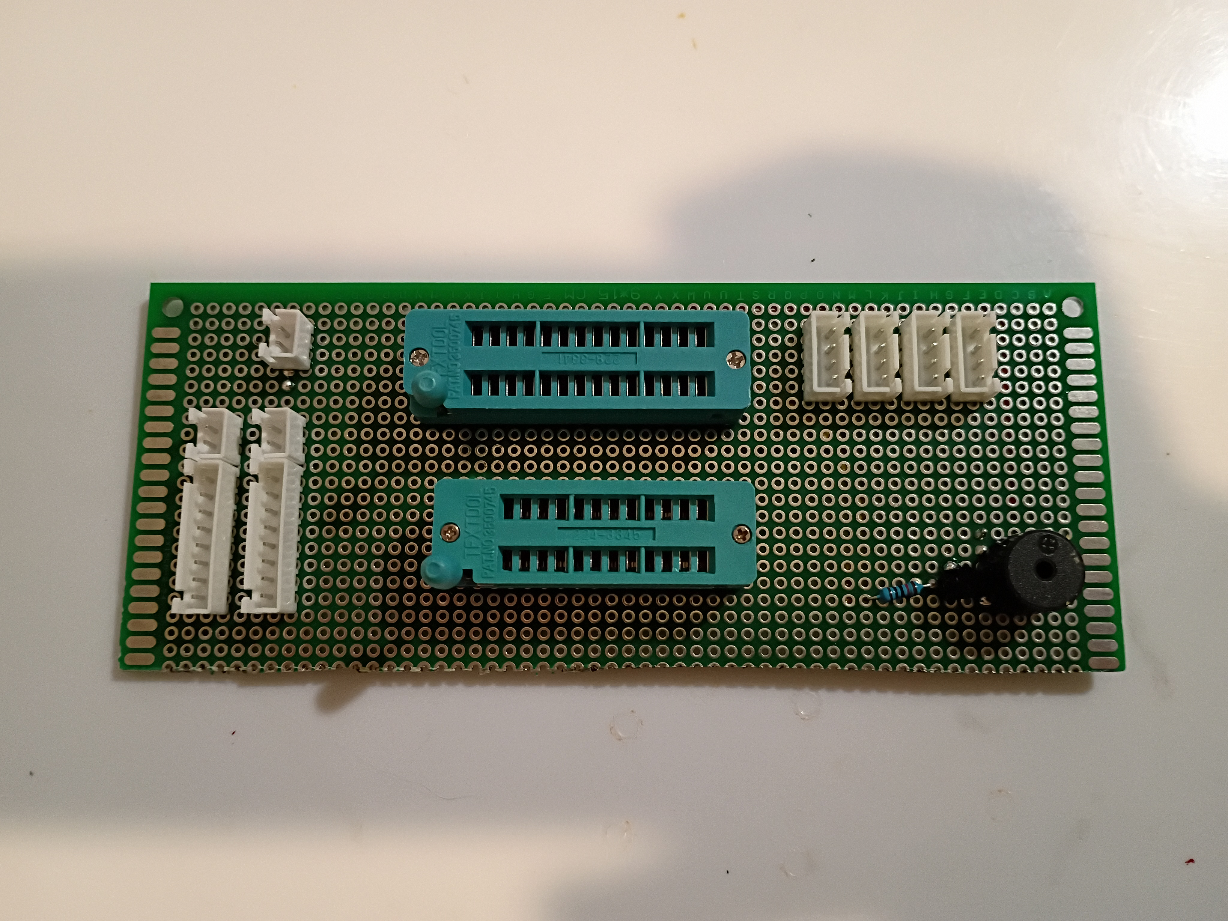
Updated draft schematic and created PCB design for the main control board using the latest PCB-etching lessons learned. This board will be fabricated in-house. See 03010-002 Kicad project.
Created draft schematic for the main control board. See 03010-002 Kicad project. 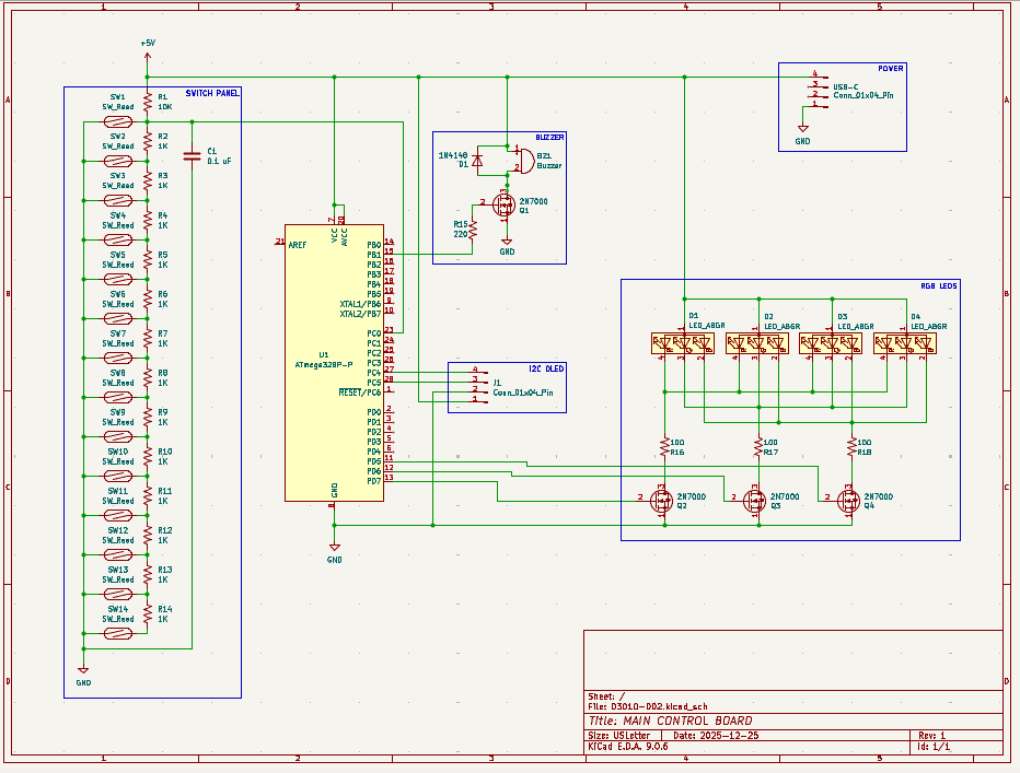
Created SVG for laser cutting & engraving simplified ruler. See project CAD directory. 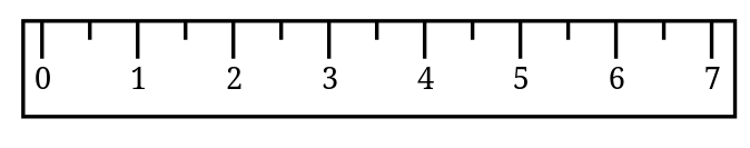
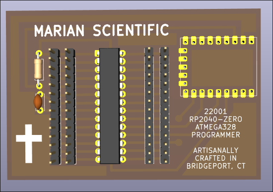
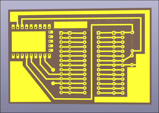
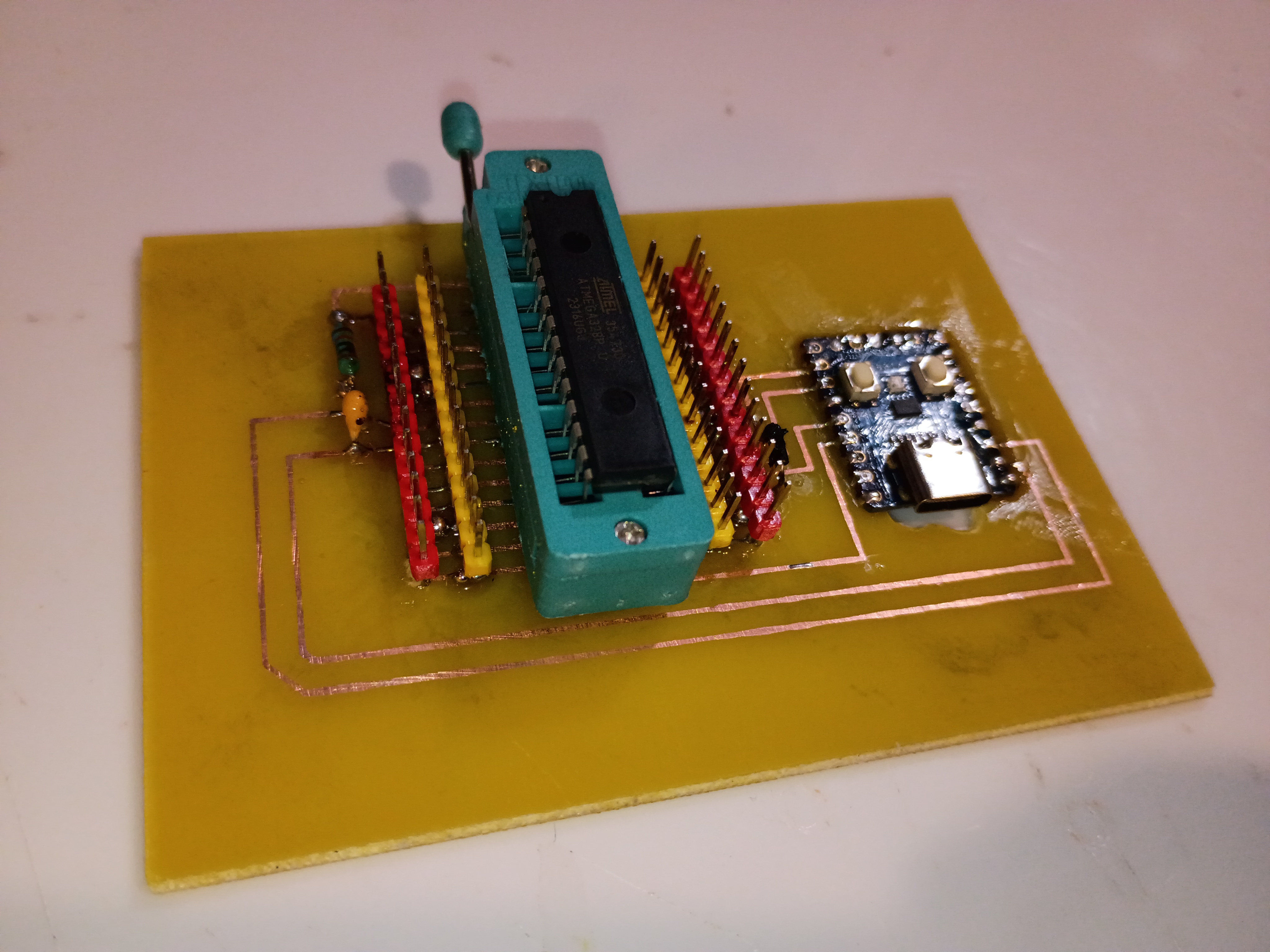
Incorporated a host of improvements to the PCB design of the 12001 RP2040 AVR programmer into a productionized version. See project entry for a list of the improvements and the CAD files. I can begin to fabricate some of these when I get back from my trip.
After brainstorming follow-on math manipulatives with the client, we are launching a prototype effort for a manipulative involving ruler measurements. As was learned on xMM1, moving parts and a tactile input device make the manipulative very engaging for the children. This manipulative will consist of a box with an exposed sliding piece of plastic that the children will need to measure. The plastic slide will be connected to a rack and pinion so it can be driven by a servo to expose different lengths of plastic to be measured. The children will need to place a ruler against the box, and to make sure they line up the ruler correctly with the start of the plastic slide, there will be a reed switch that detects that and shows a green status LED. When the measurement is made, the child will be able to select the value (in half-inch increments) using a pegboard, by putting a peg with a magnet into the corresponding marked circular slot. The different values can be connected to a series of resistors to be able to detect the voltage value with a single ADC pin, versus having to waste a lot of GPIO pins. If the rack and pinion approach does not work due to space limitations, a servo-controlled paper scroll can be used instead.
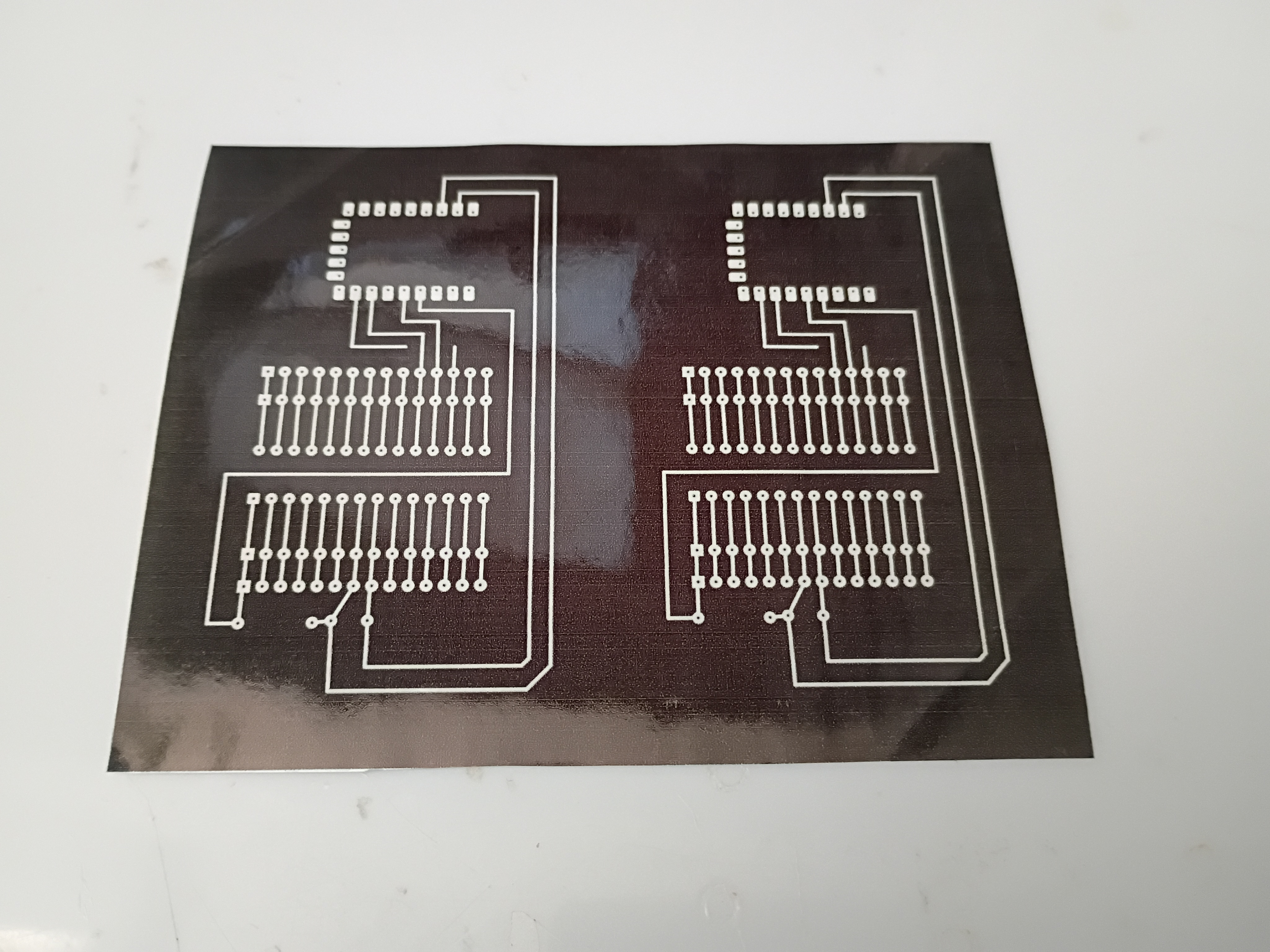
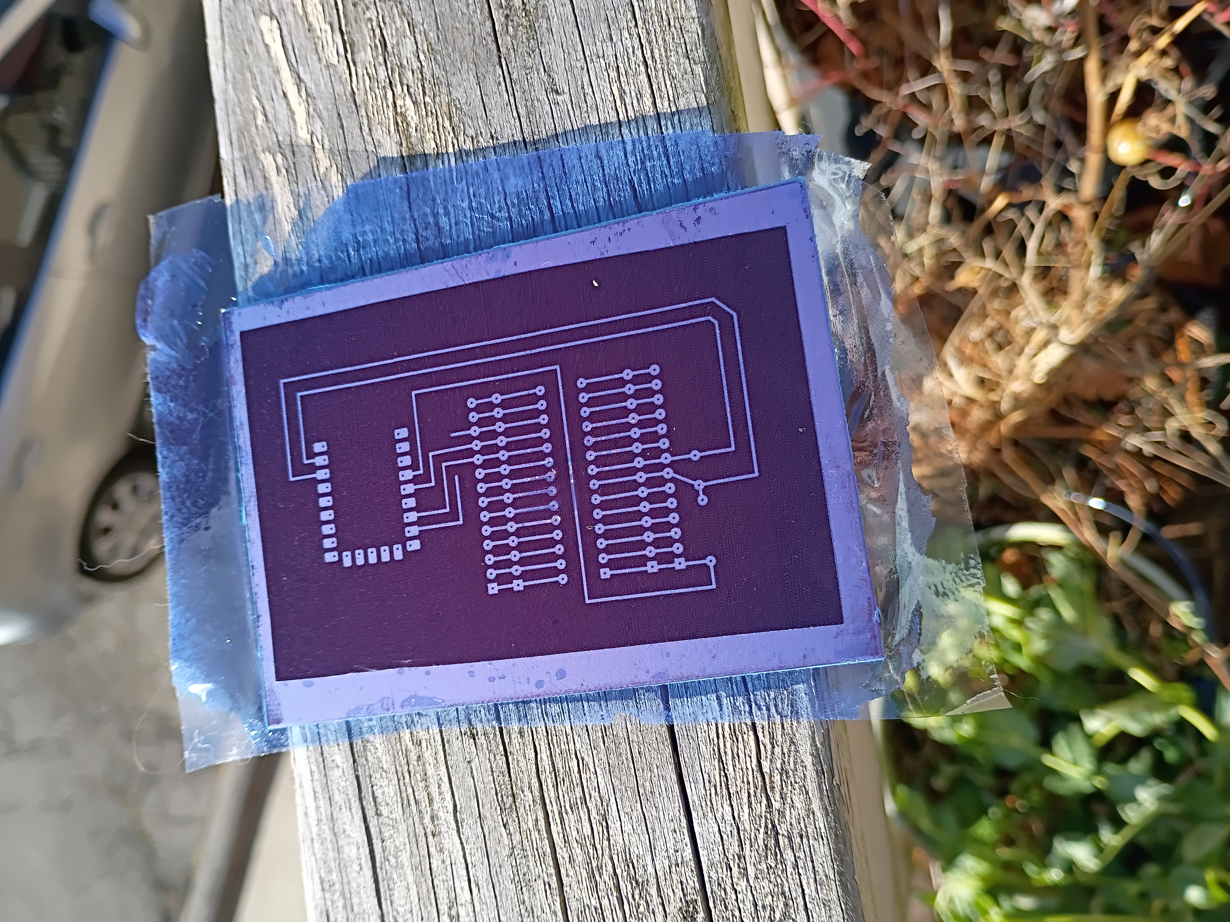
Designed programmer PCB and attempted to create a DIY PCB at home using etching solution. See video of it in action.
First two attempts were using photoresist, so the mask was negated.
I didn't have a reliable source of UV, so I used the New England winter sun...
...which overexposed the photoresist after 10 and even only 5 minutes. Also I had bubbles in the film because I applied it with a clothes iron, whereas a laminator would have done a far better job. In any case, these two attempts failed.
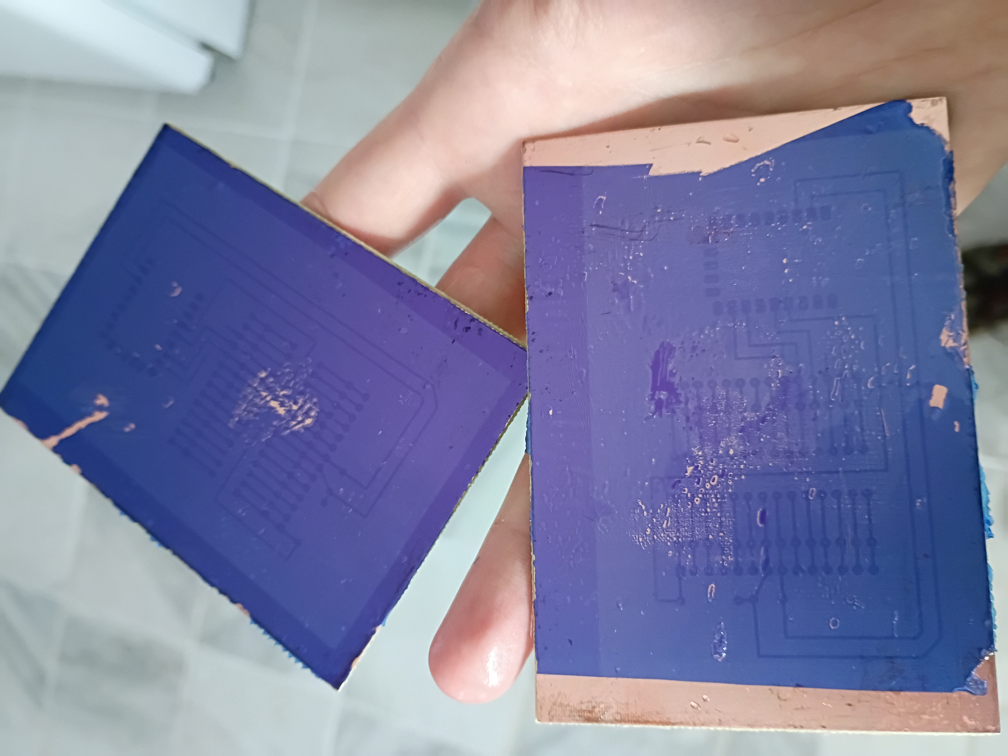
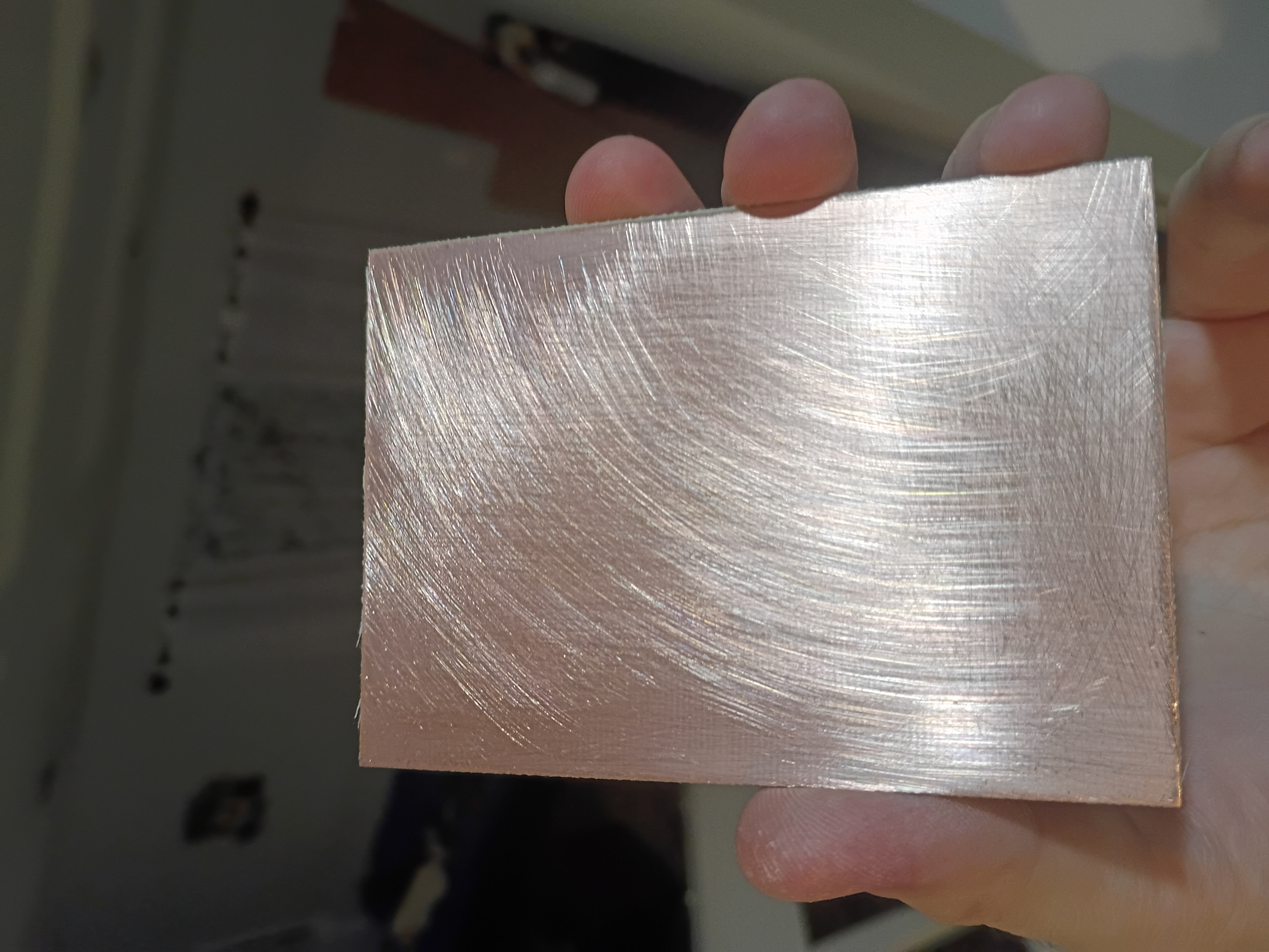
So I tried the toner-transfer method. I did a much better job of cleaning and scuffing the copper-clad board using 240-grit sandpaper and acetone.
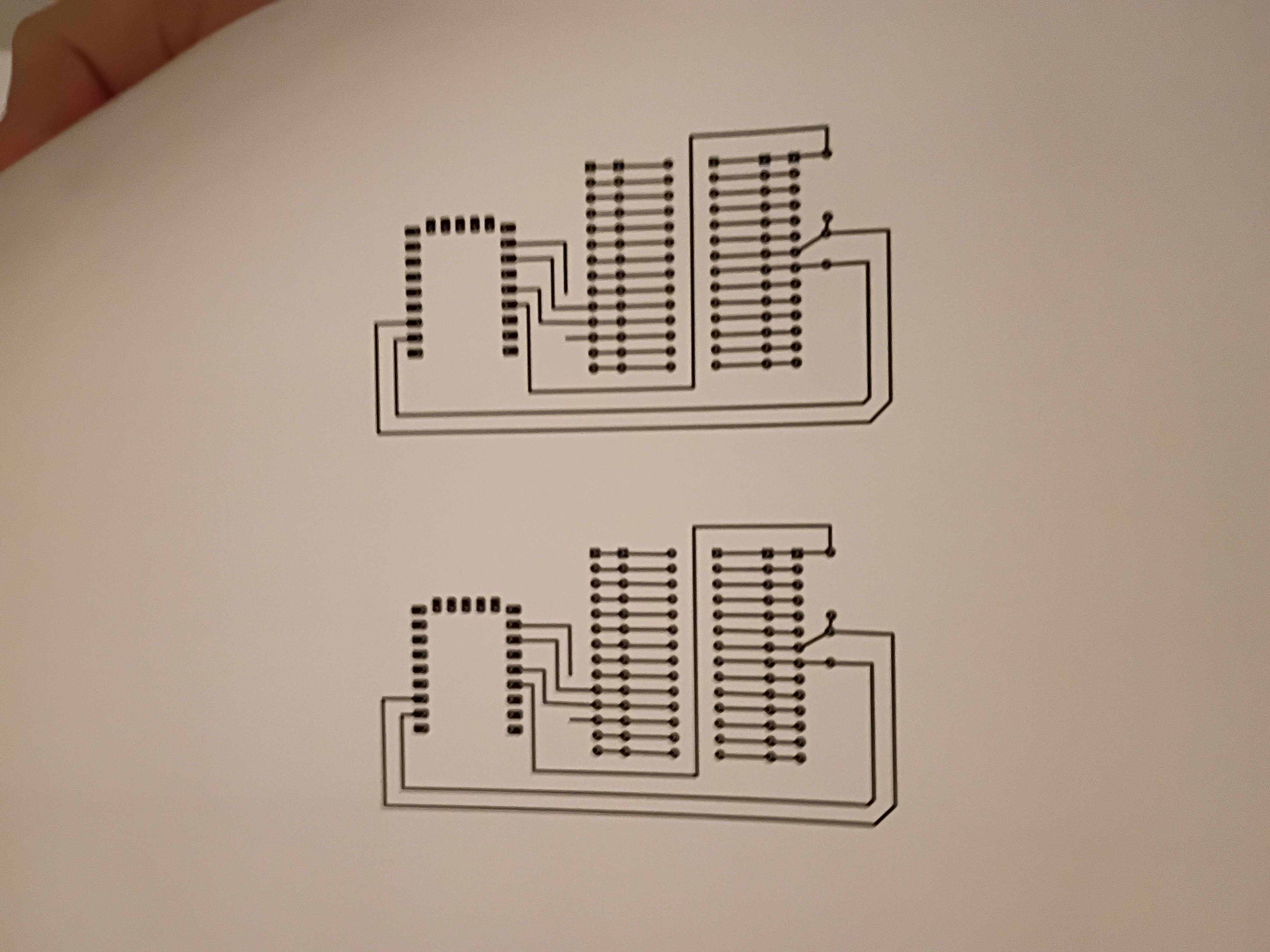
I printed a non-negated (and unfortunately mirrored, a mistake) plot on glossy paper using a laser toner printer.
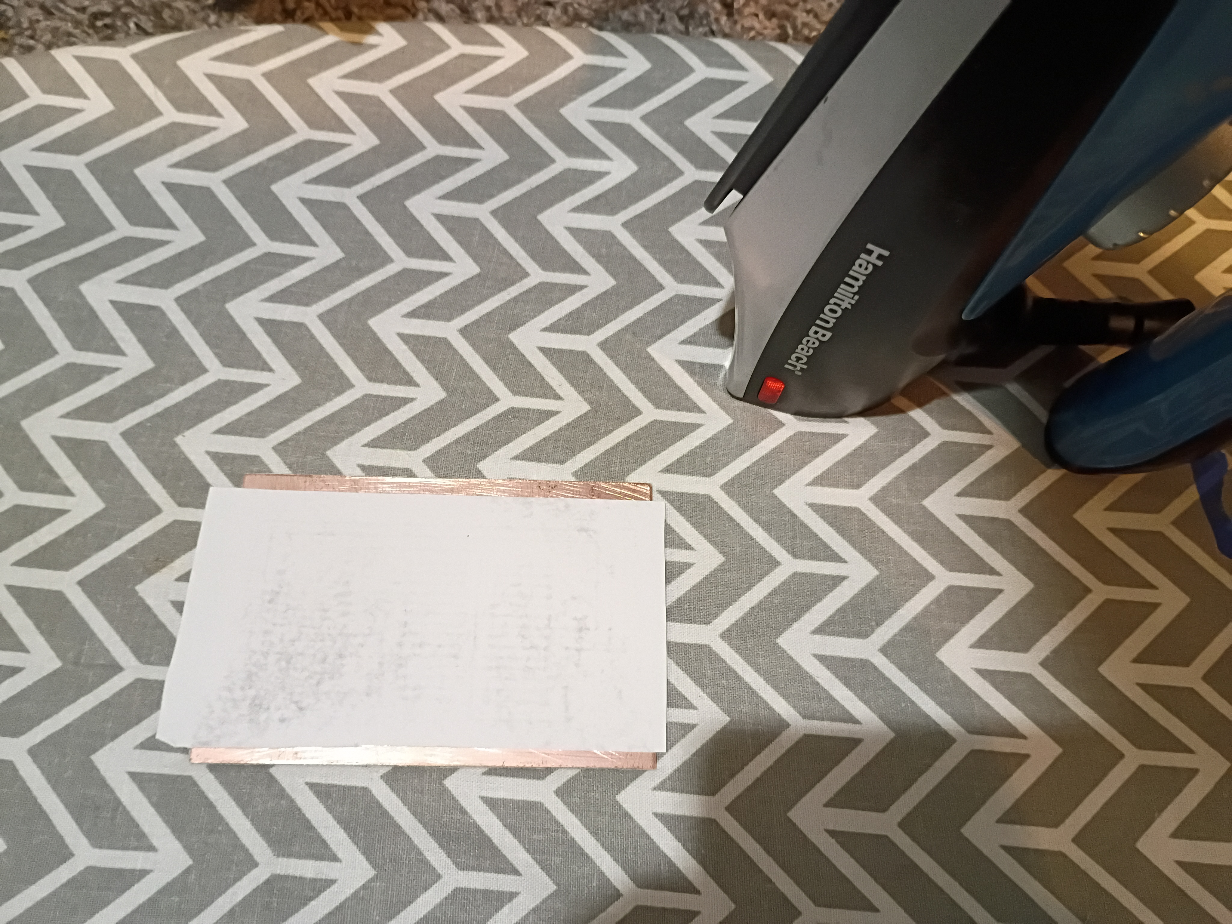
I ironed the paper onto the copper-clad board,
...and dissolved off the paper over 30 minutes in some warm water. You have to get everything off, even the white paper haze that might find itself between pins and traces that will otherwise prevent the etchant. Noticed I failed to do this on the right, where the RP2040-zero mounts.
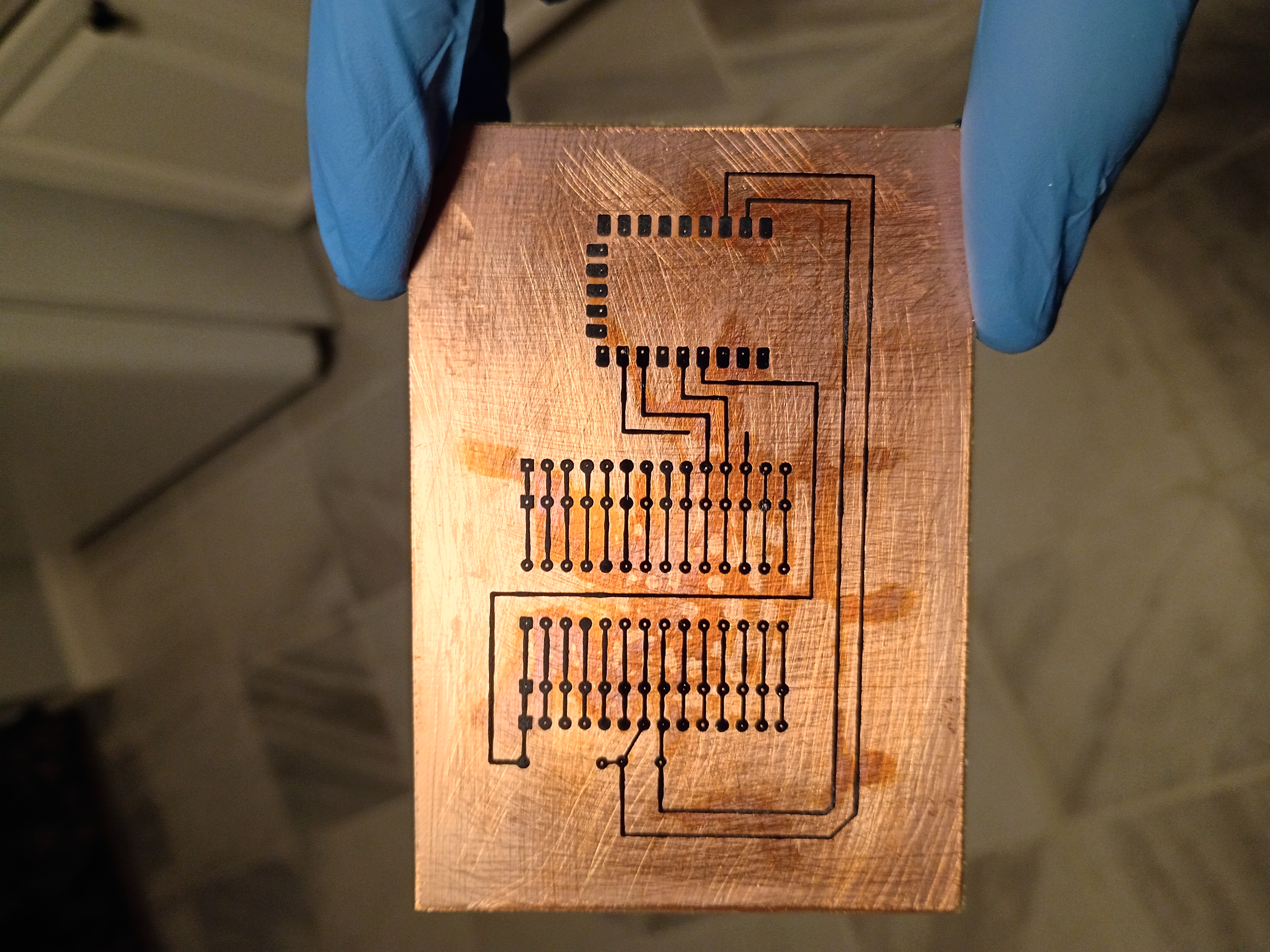
Then I set the board in Ferric Chloride and gently agitated it for 10-15 minutes outside. If I had made most of the board the ground plane, it would have gone a lot faster because less copper would have needed to dissolve away.

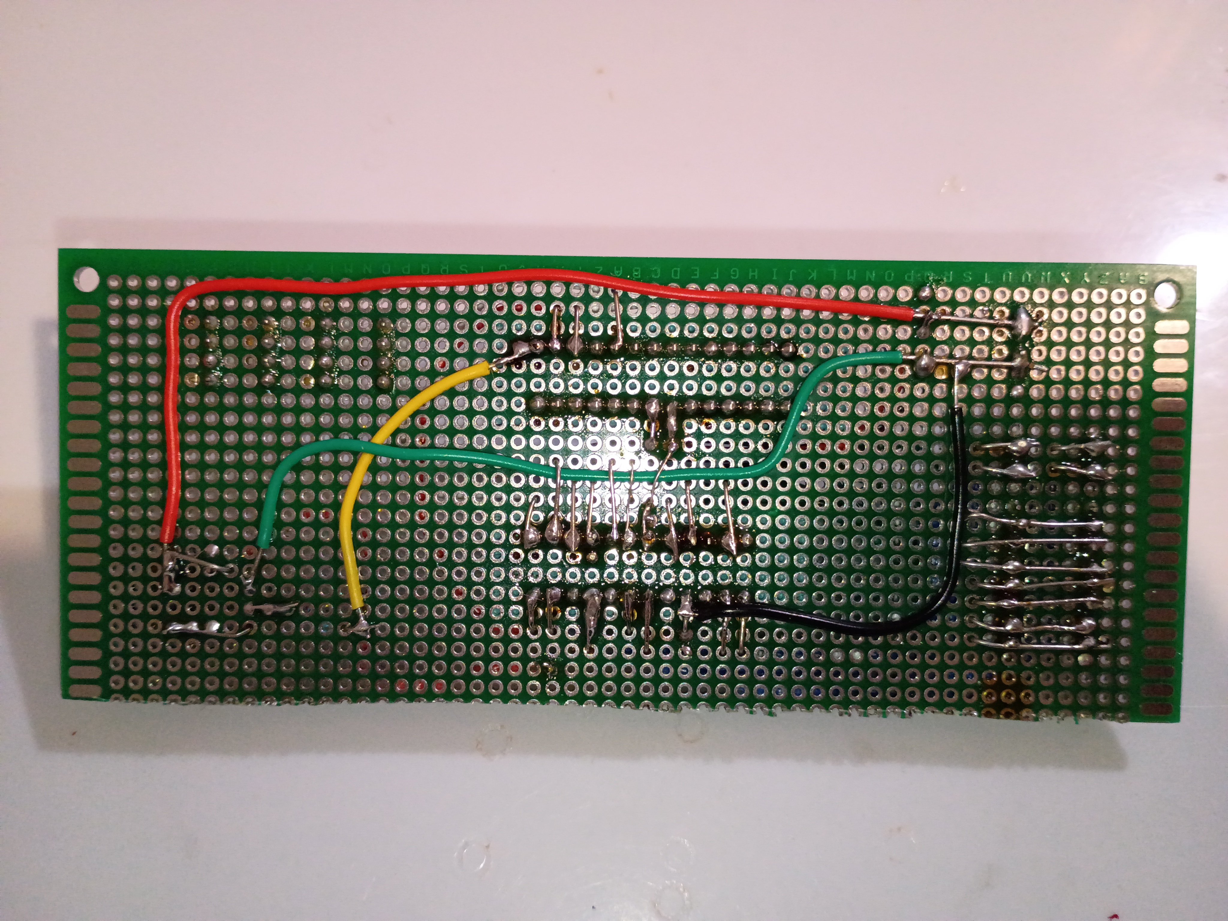
It turned out pretty well, but notice there was still some copper between the pads on the top of the board.
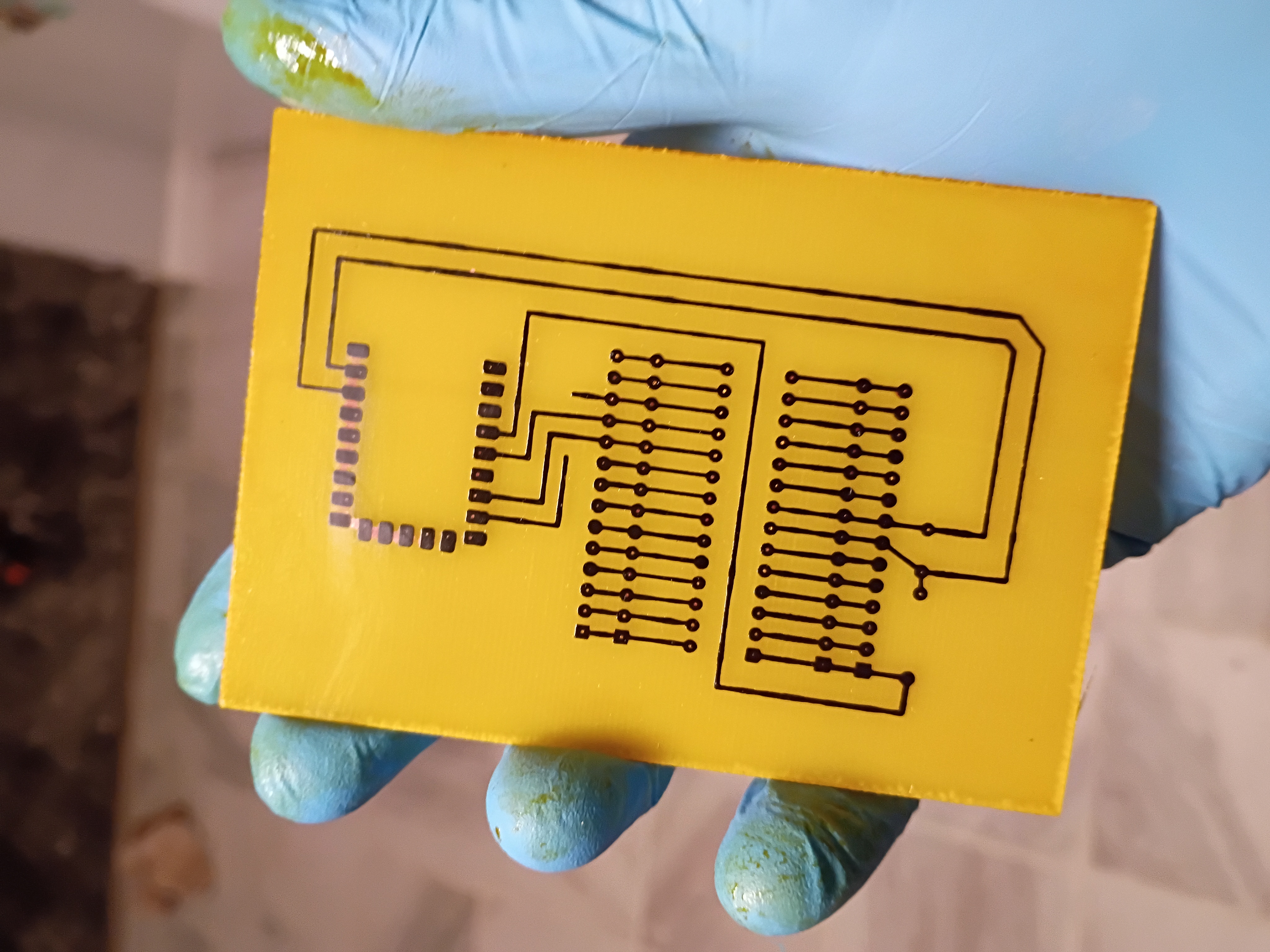
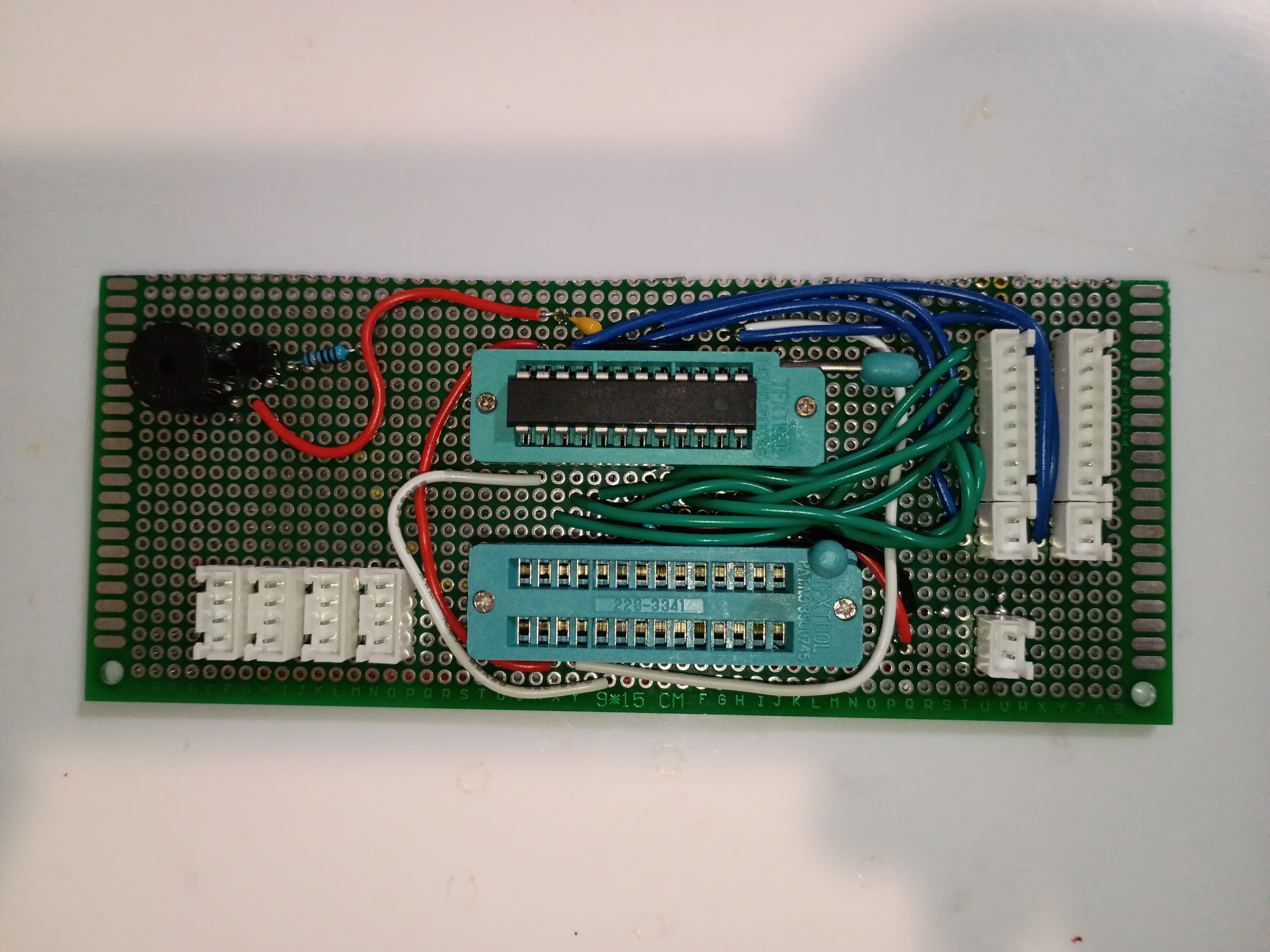
So I wiped the remaining toner off with acetone and popped some holes in using a very small 0.8mm endmill. In retrospect I should have made the copper pads larger, because I drilled out most of the copper even with my smallest endmill. I also drilled out a hole for the underside of the rp2040-zero board, which although it has castellated edges, cannot be set flat on a board without cutting away the board beneath it. Then I began soldering components. Again, in hindsight, my traces should have been on the opposite side of the board as my components, because they were extremely challenging to solder because the pads were directly beneath. In the future, traces should be on the background copper face if the components will be mounted on the top, and that would not have required that I even mirror the board plot in the first place. I could have also toner-transferred some nice-looking component labels and even a part number if I had set the traces on the opposite side as the components. Either way, this investigation was a learning experience, so I don't mind the soldering challenge and all the other added complexity.
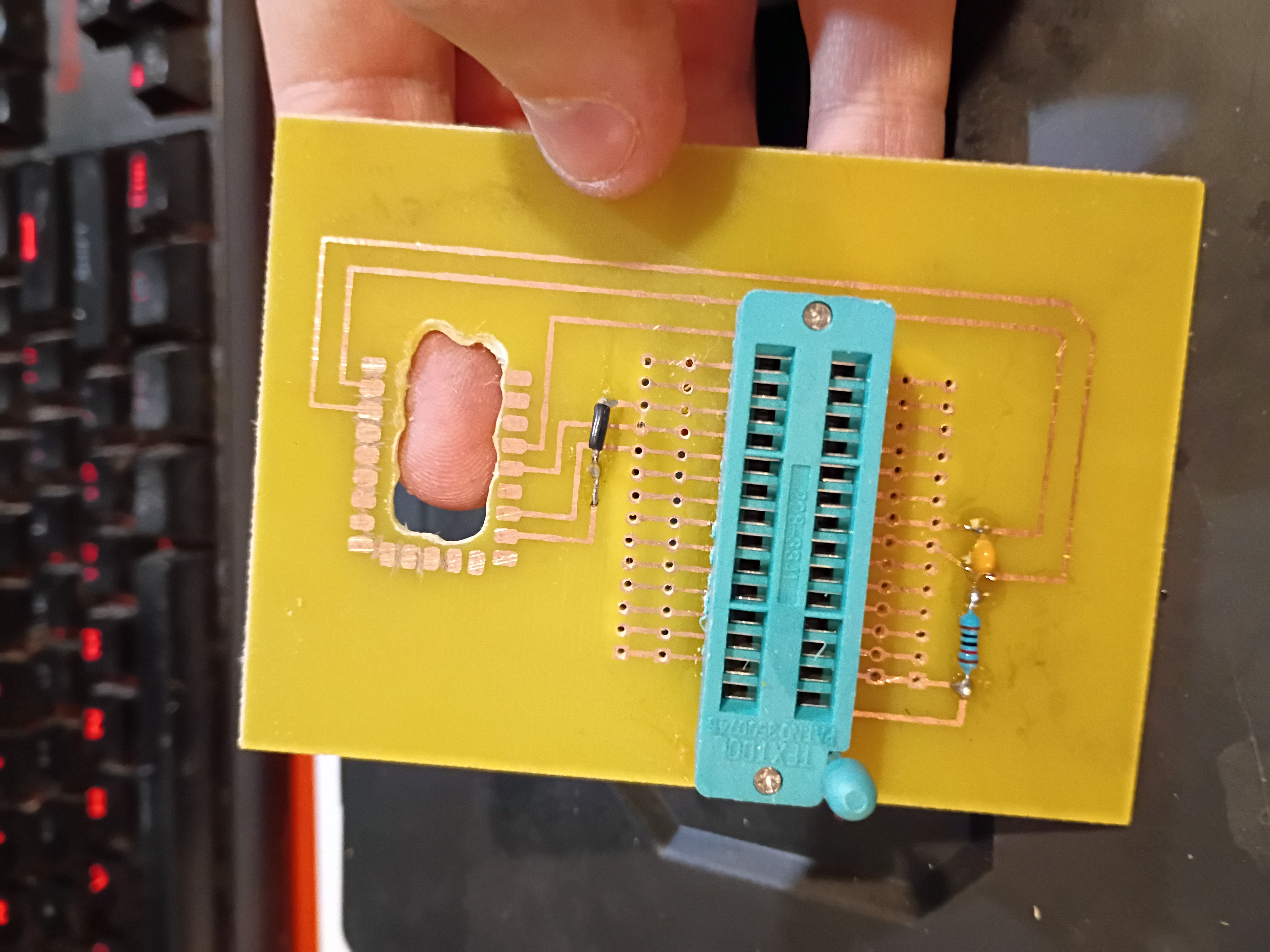
The photos below show the final product which actually works well as an Atmega328P programmer; I tested several blink programs. The rows of header pins also almost make this into an Arduino-like devboard, though it lacks any external oscillator or other peripherals. I did have to shave down the bottom of my USB-C cable so it could come in flush. A lot about this whole project could be improved significantly, but I had a lot of fun with it. This investigation was a massive success, and we did barely manage to complete it on schedule.
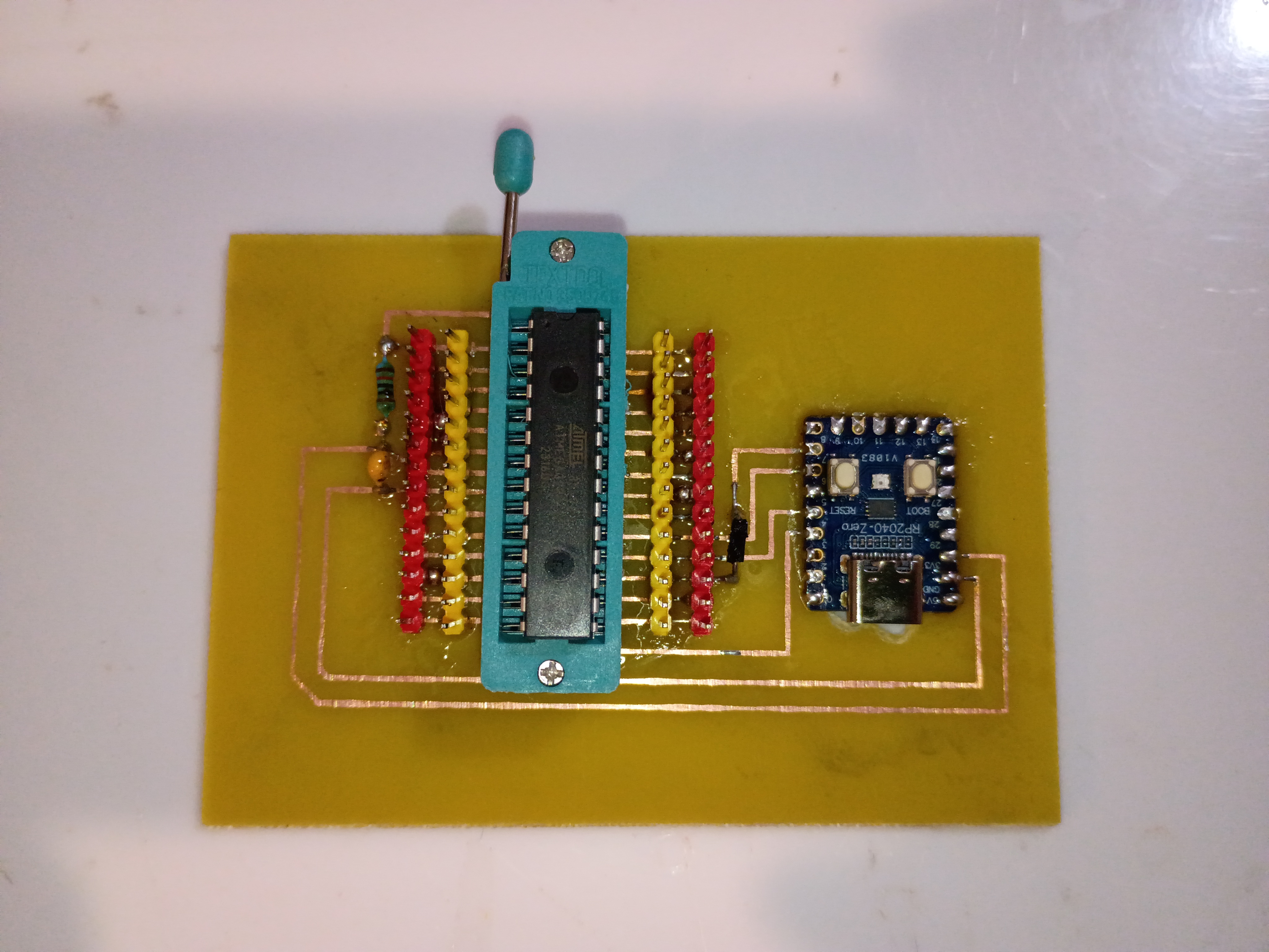
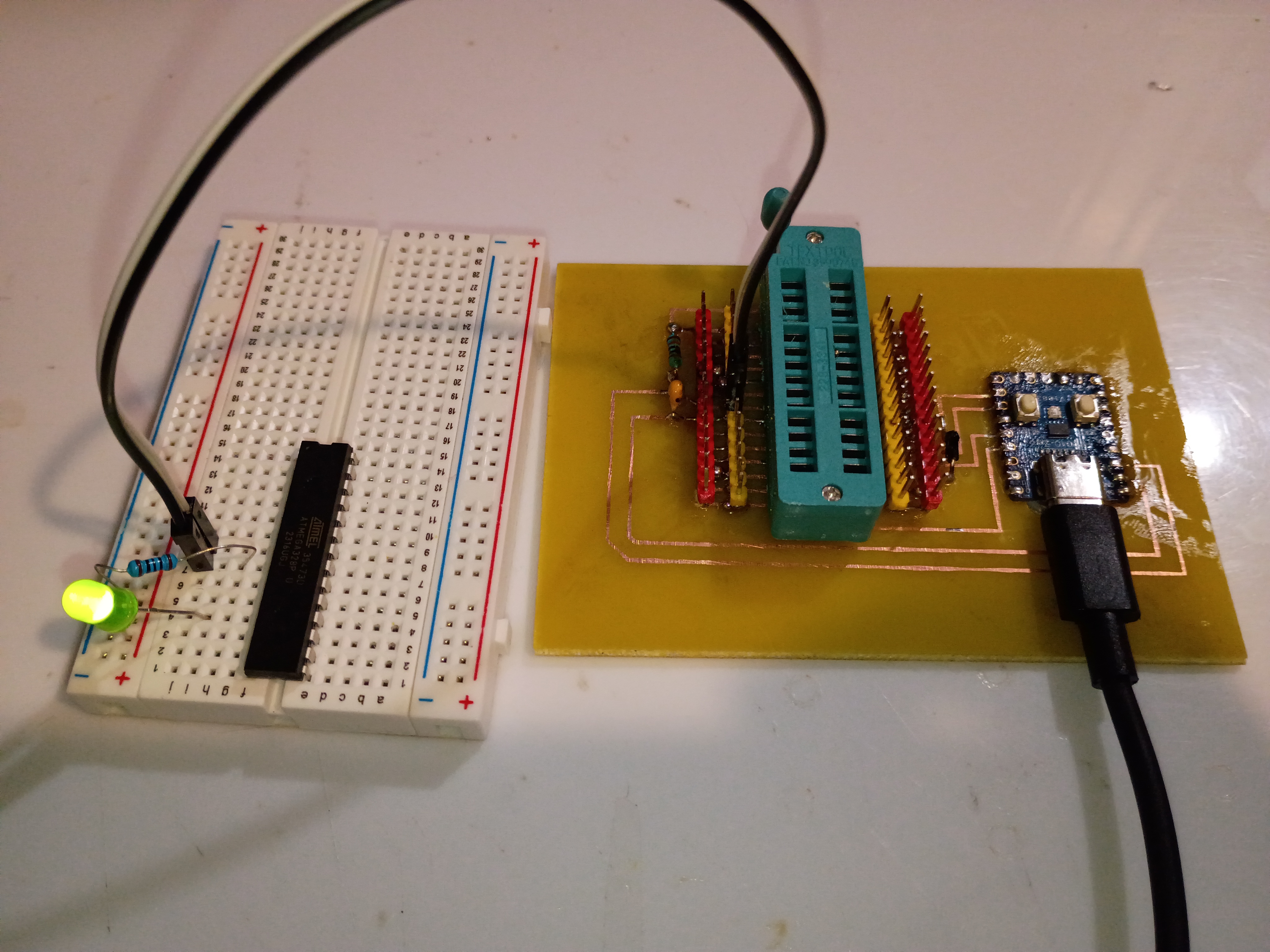
Got the programmer working, which was a combination of the code running on the RP2040 and a Python script transmitting the serial data over USB from my PC. See video.
Wasted ~2 hours today alone tracking down a very dumb mistake - I was off by one on the SPI pins on the Atmega328. No wonder I wasn't getting a response. I completely obliterated the code trying to track it down, so I will reconstitute something clean tomorrow. The AVR chip nonetheless acknowledges our attempts to program it now. 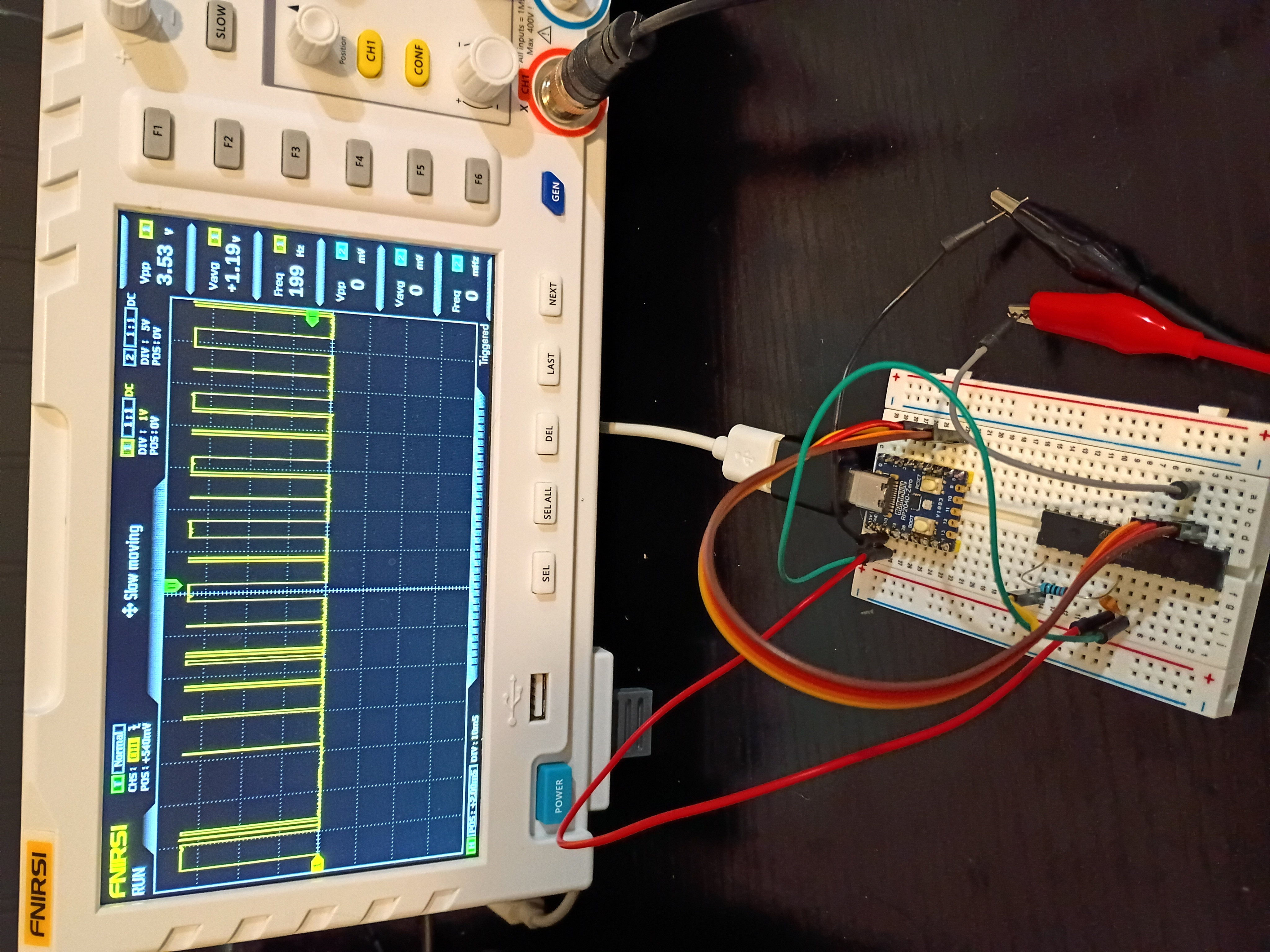
Finished a likely buggy implementation of both the rp2040-USB-programmer and the PC-based hex file transmitter using python. See code directories 005 and 006. The clock and data transmission works as expected, but for some reason the Atmega328P is completely unresponsive; no signal is being transmitted back over MISO. 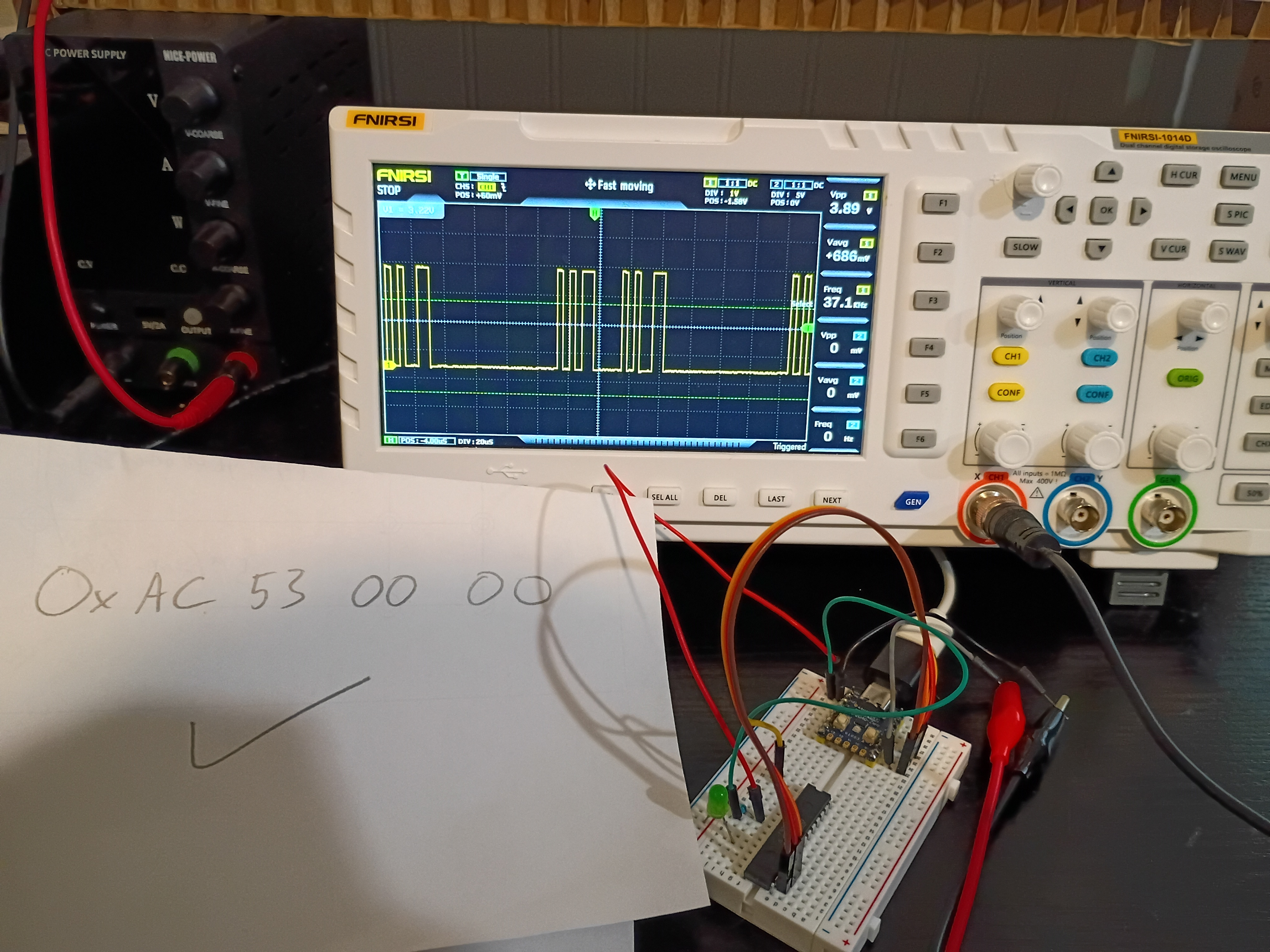
Soldered pins to the RP2040-Zero board for preliminary breadboard tests. Got control of the built-in RGB LED working over PIO (very interesting and powerful) and began working the ICSP algorithm. Link to top-level project directory..
Launched short-term investigation into developing a RP2040-based programmer for AVR ICSP-capable chips, especially the Atmega328P. After internal discussions 2025-12-14, both of these chips seem to be the best avenues for future electronic project development. Completed first three preliminary tasks establishing a functional Atmega328P and RP2040-zero toolchain to complete the remainder of the investigation.
Received 6 of 6 (no extras) 03007-001 stepper coil-driver PCBs from OSH Park. They arrived in 15 days. The communication from the company was far better than DKRed. The board quality is decent, and the price is comparable. Boards (purple cheapest and default option) do come with jagged edges where they are broken from a larger PCB platter. I do prefer them to DKRed. 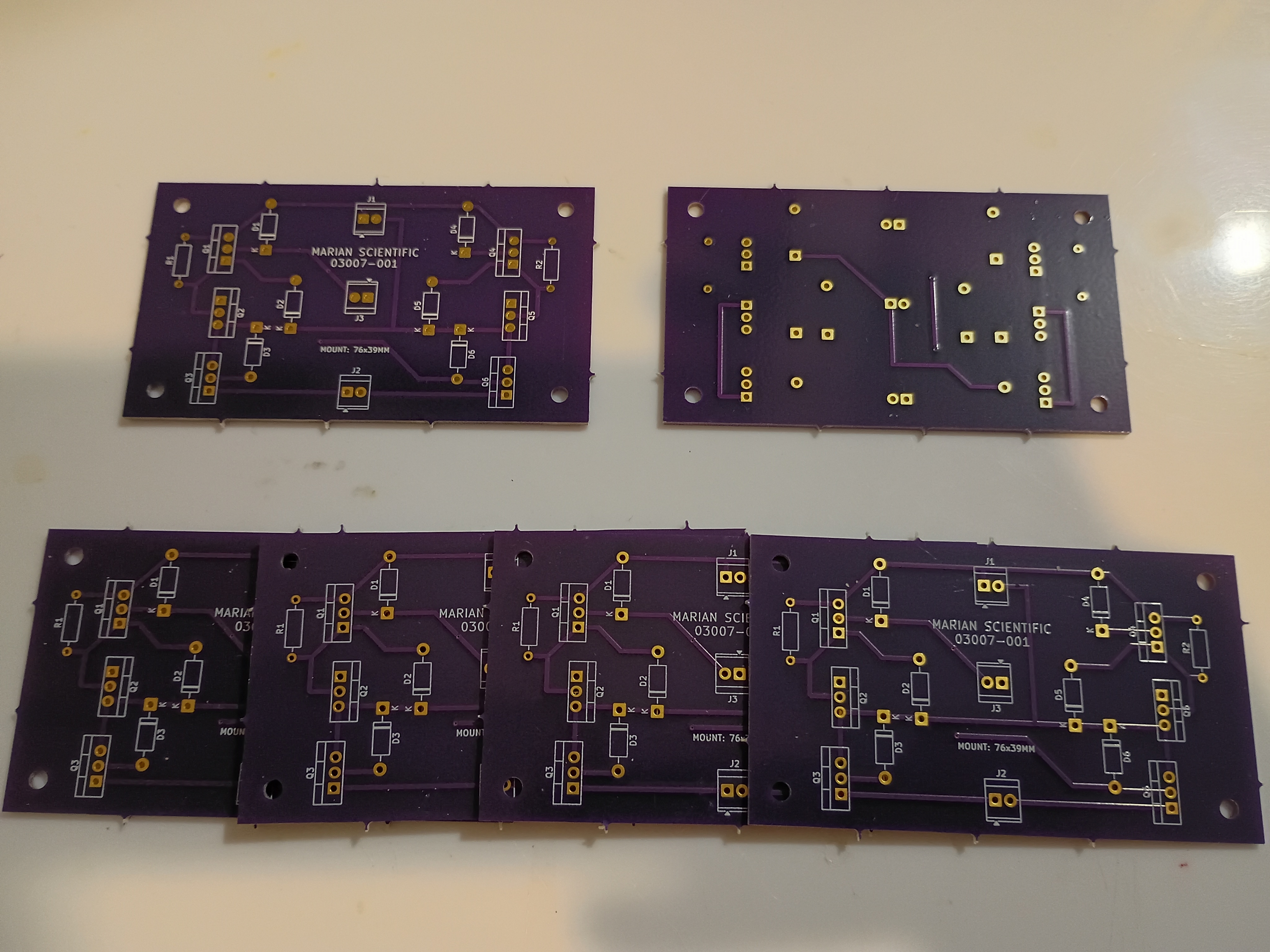
Recorded final video of manipulative working. The prototype will be used as a template for a future productionization effort and, afterwards, permanently donated to the test classroom.
Tested the project with 6-7 year olds, and it was a massive hit. Kids were fighting over the 3 magnetic input blocks, and I kept a half-dozen or so busy for around 15 minutes during dismissal. They thought it was professionally-made. I think one factor about the manipulative that they enjoyed was the tactile nature, which is not something familiar to them in an age of touchscreen-everything. 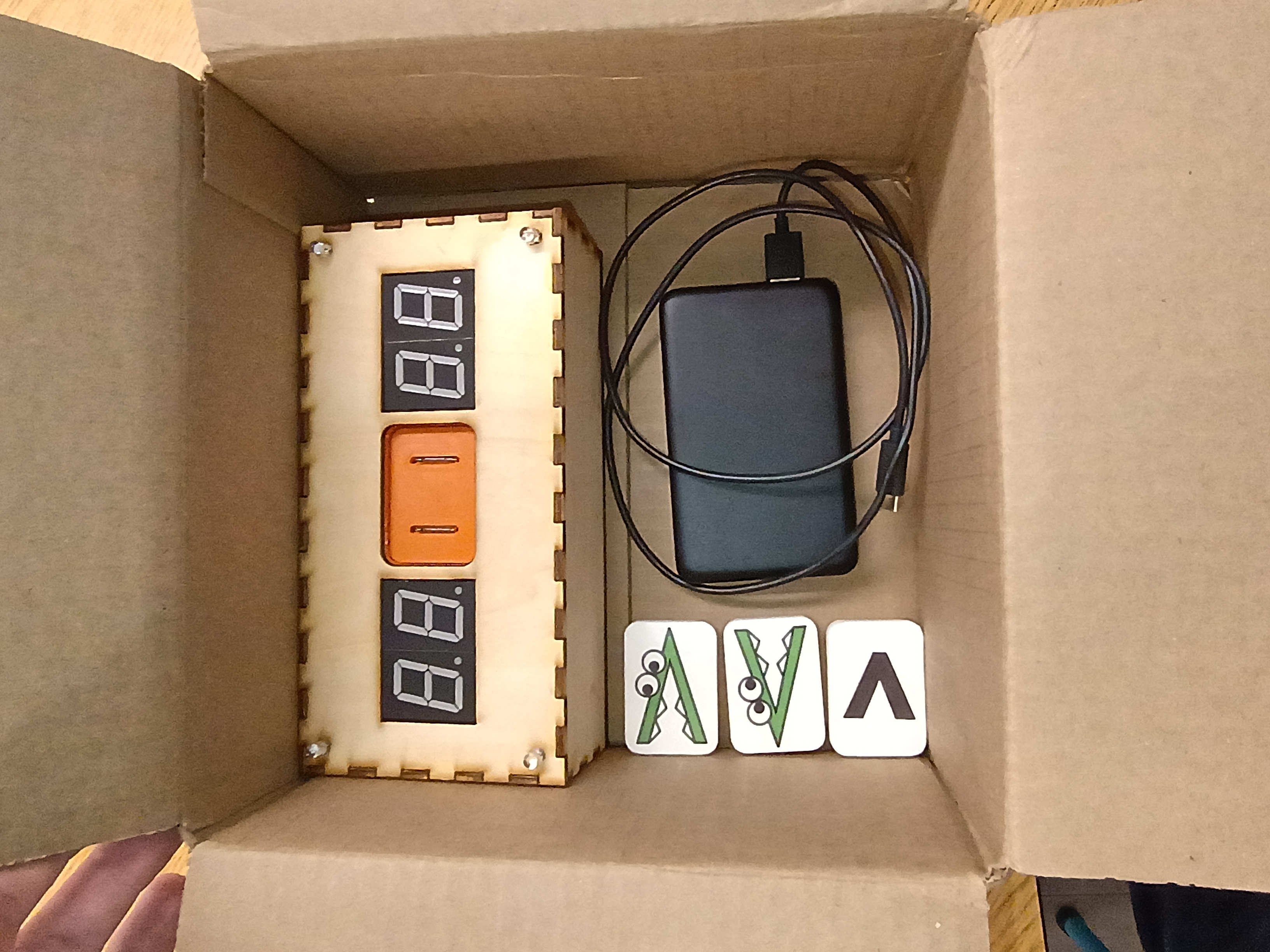
Project complete 3 days early. Made final updates to the full project code to fix the RNG and the intermittent failed 7-segment initialization. Also somehow the power draw is now high enough that it doesn't seem to automatically shut off the USB power bank, though the power bank still reads 100% after 3 days of testing. Designed a new 03008-010 input block with standoffs and a bigger grip area. See latest CAD. Printed two versions in new white PLA and applied the 'Alligreater' image (one mirrored) to the front with a glossy transparent parent sticker. Will test this device with the children tomorrow. 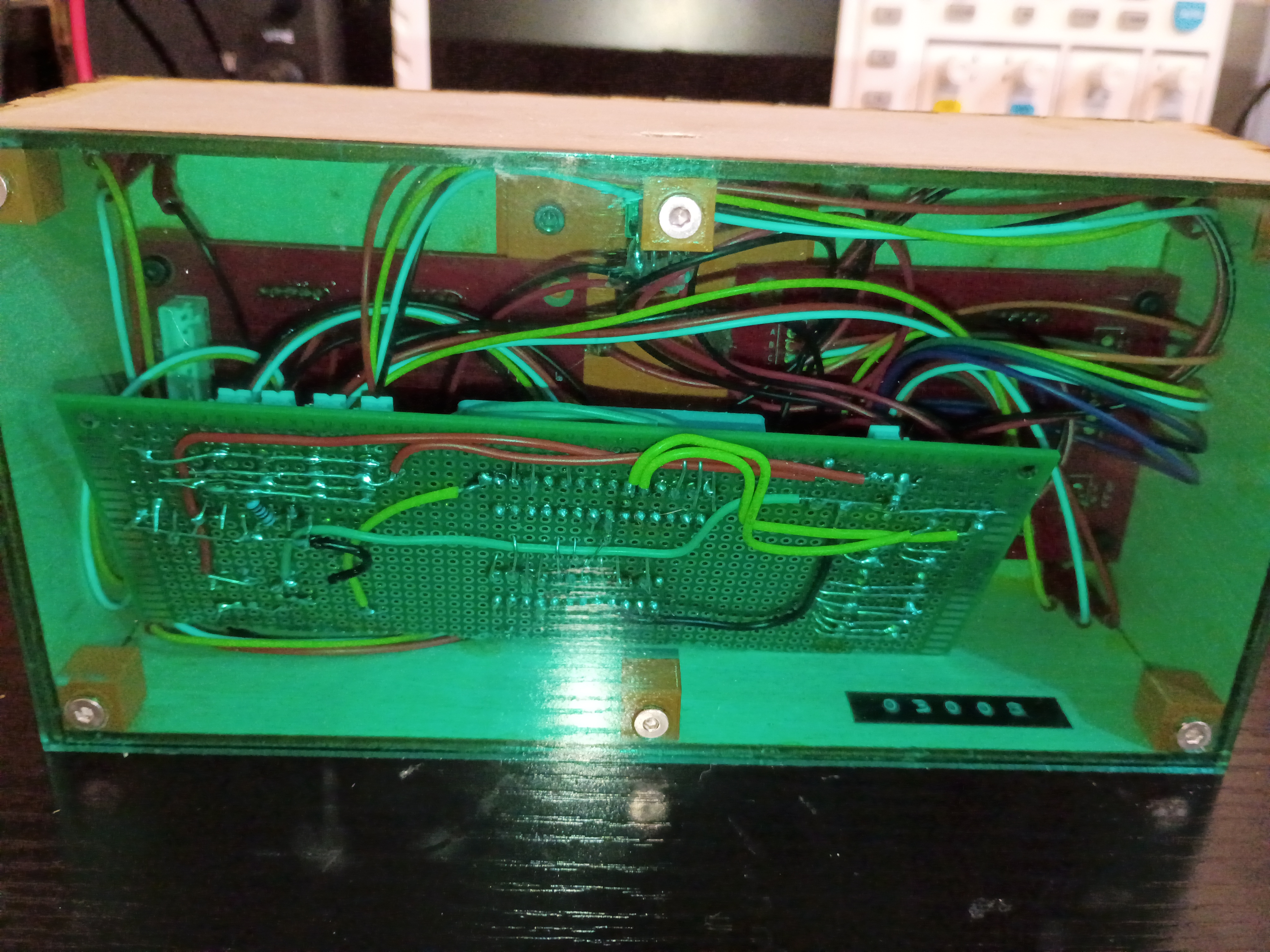

Updated the full project code. Entire project essentially works - including the buzzer, RNG, LEDs, magnetic inputs, etc. See video of it in action. Still needs an improved input block and there is still a glitch where it sometimes initializes with 88/88 on the displays.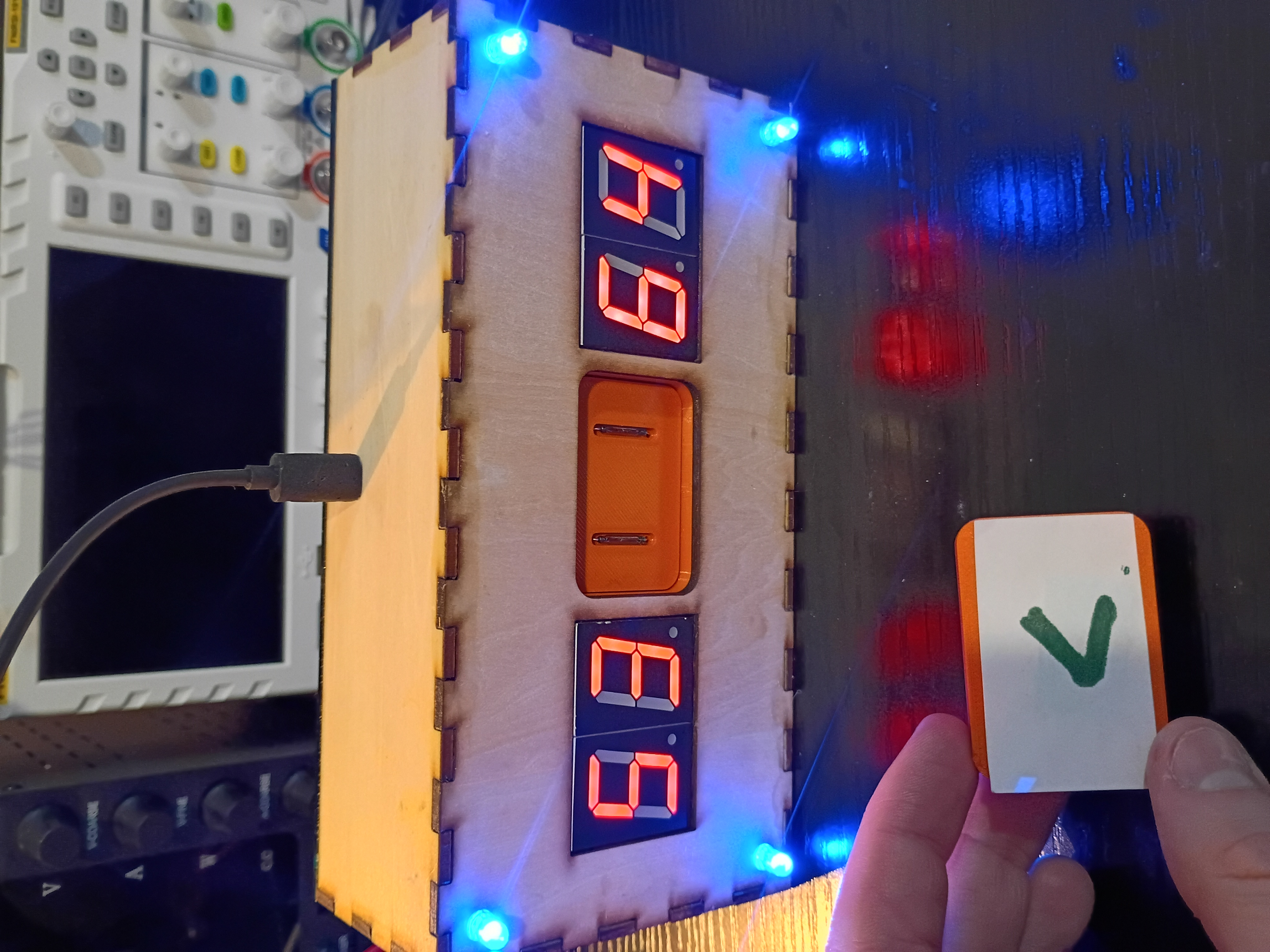
Toyed around with the code for a while, but there is something amiss with the buzzer control timer and the rest of the control logic, so I implemented a buzzer-less version. Had to improve the solder connections, but everything fits in the box pretty well. Needs to be cleaned up slightly. See video of it in action. 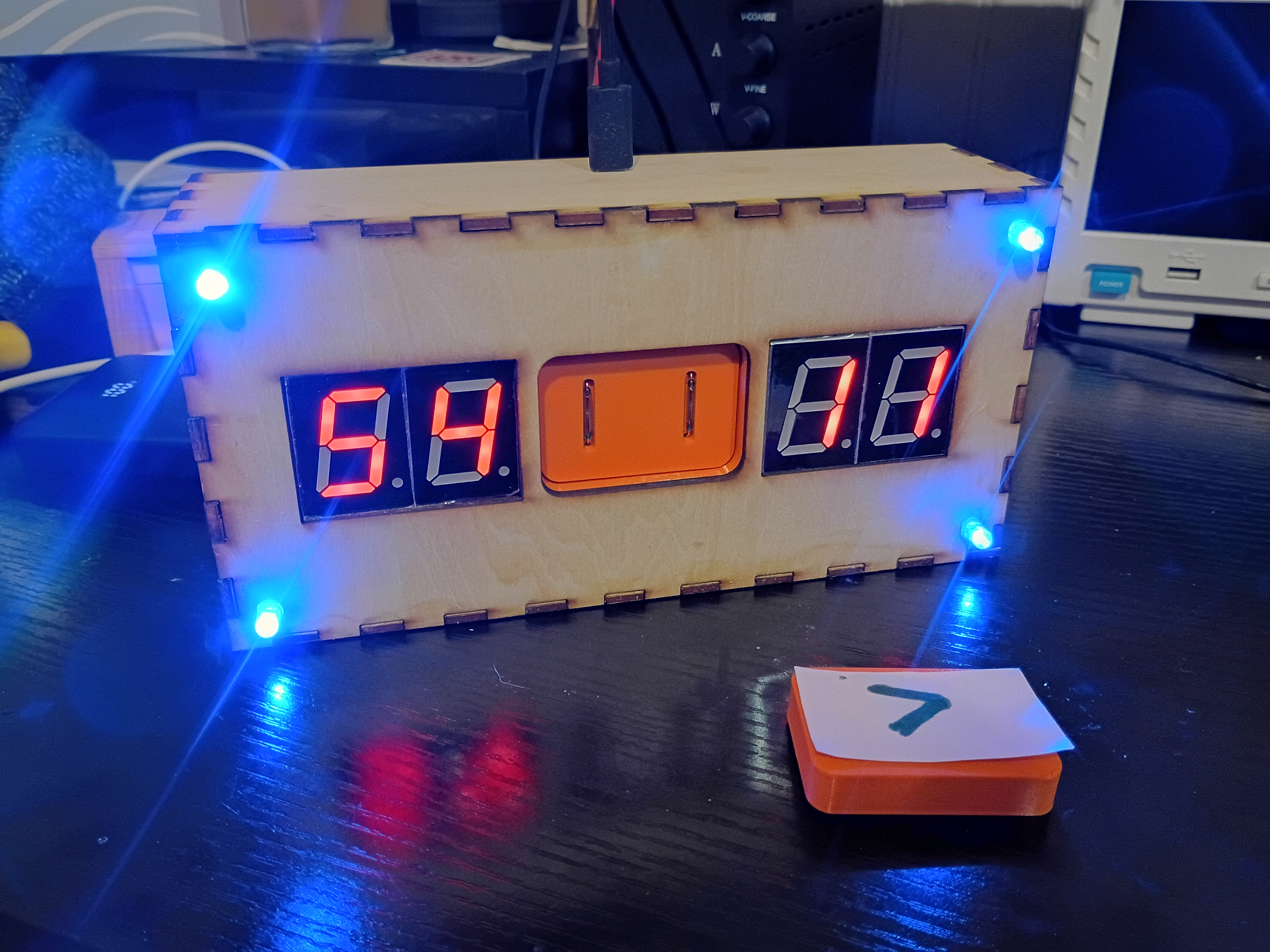
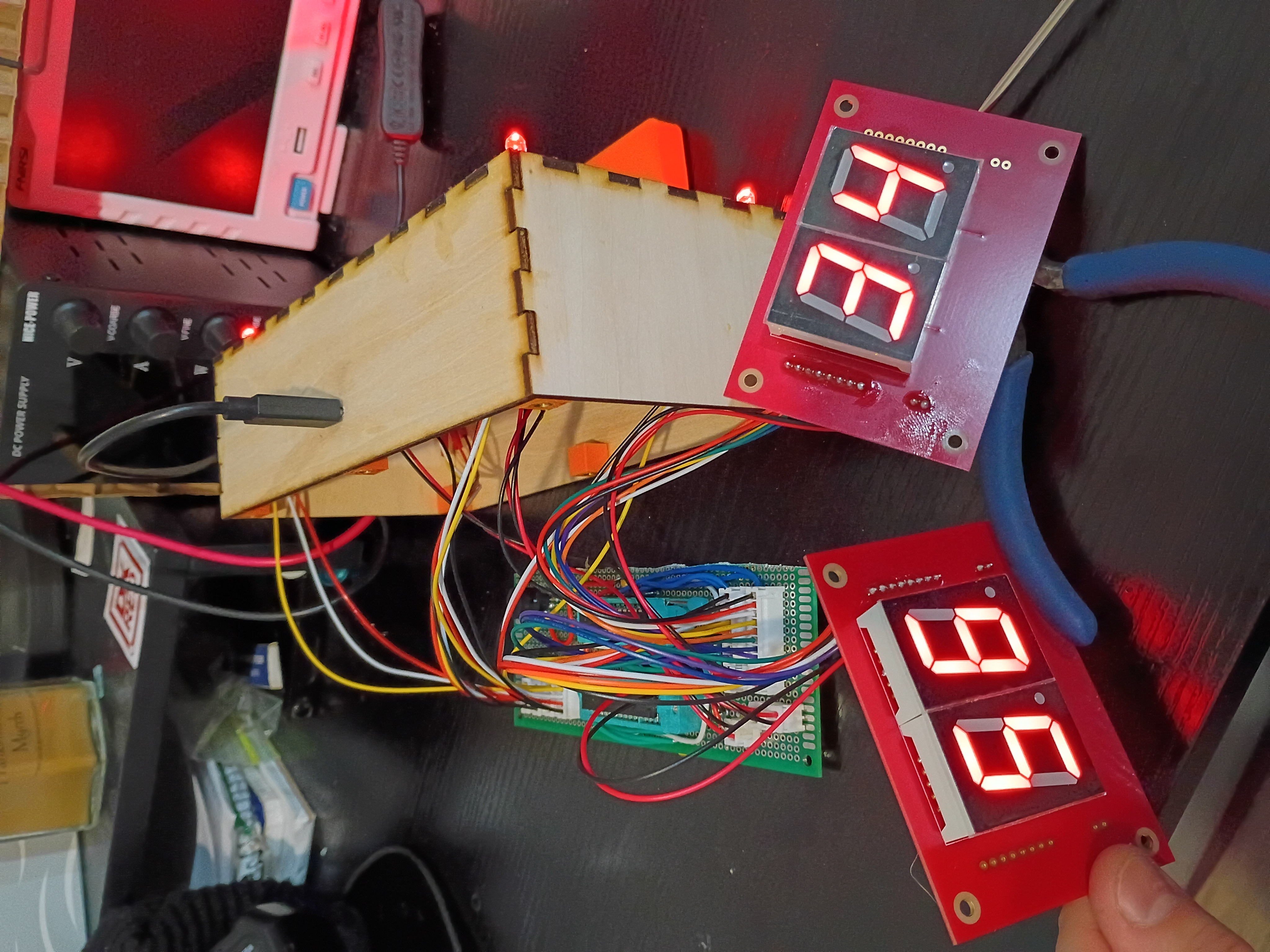
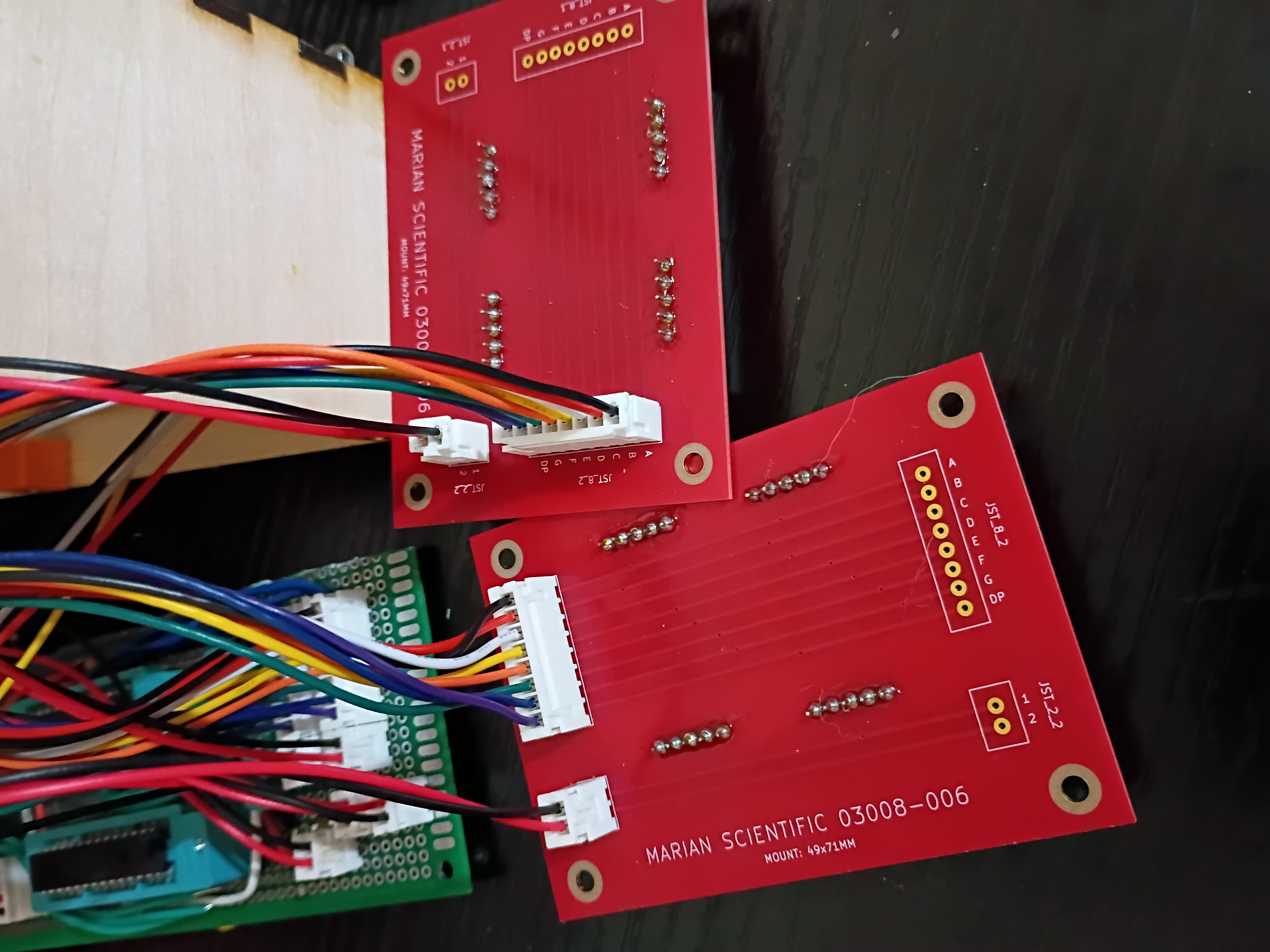
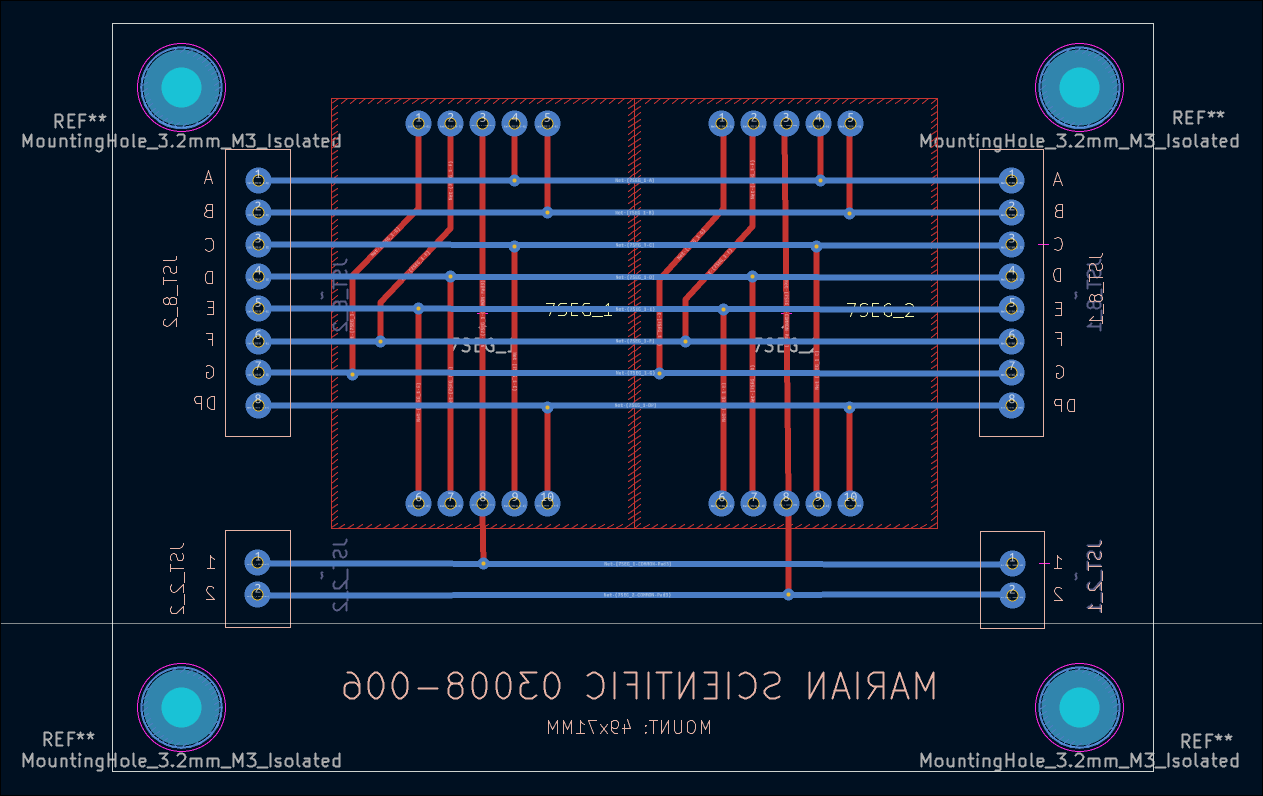
After 2.5 weeks, received 03008-006 PCBs from DKRed. Board quality very good, no mistakes were made on my end or theirs. Silkscreen font kind of squiggly in places. Overall experience was positive, though very slow. They sent 2 extra boards (6 instead of 4). Should probably make the thru holes slightly larger next time. Soldered 7-segments and JST connectors to the PCB and tested some sample code to display digits. There is some software/hardware glitch that is interfering with the buzzer and LEDs. Also, had to hand-crimp the individual JST metal pins to each wire using needle-nose pliers, as the junky JST crimpers I purchased are terrible. I also prepared two additional boards to be shipped out to support the 03009 project. 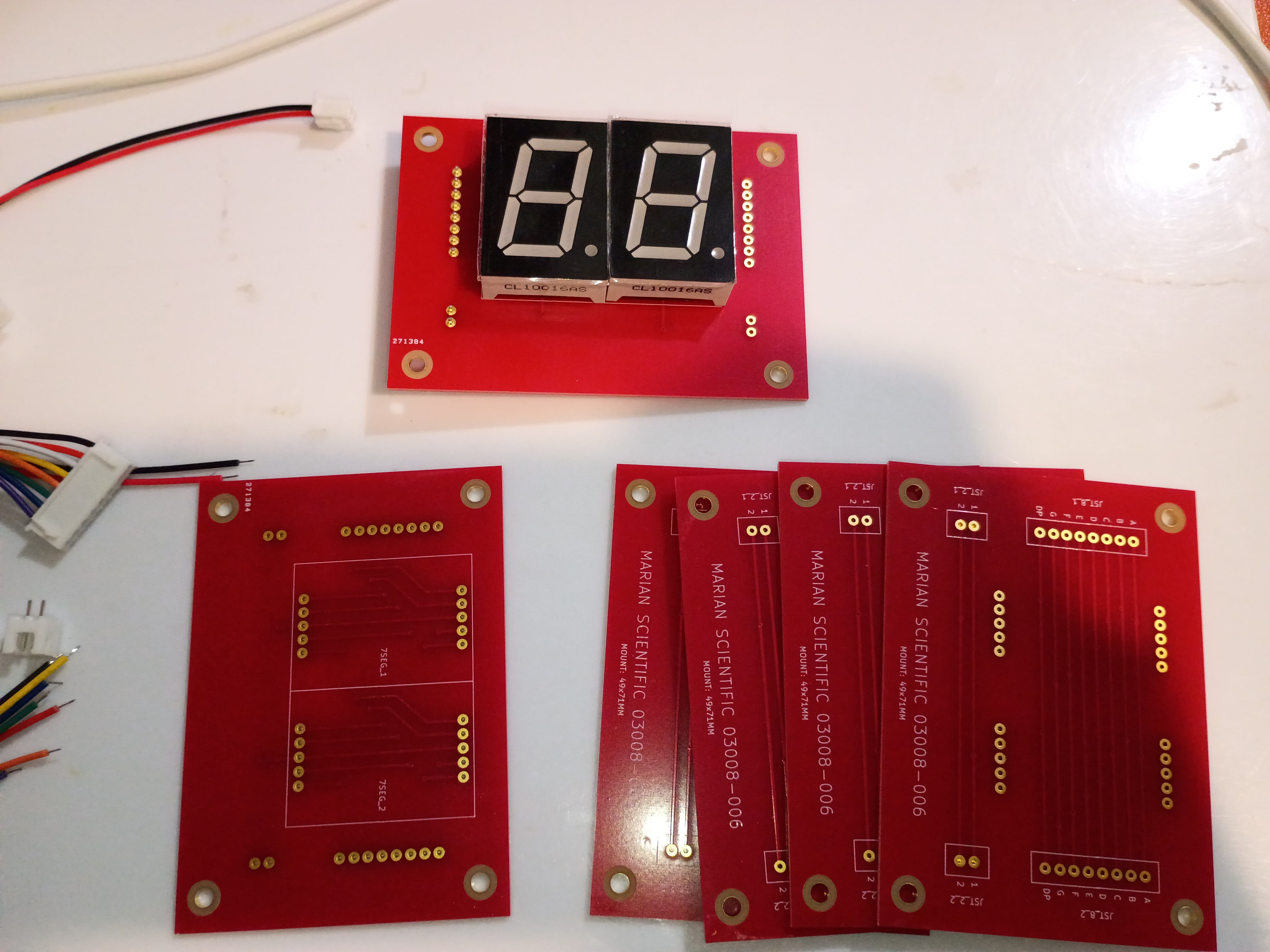
Behold a rasterized version of my 'Alligreater' SVG to be either laser engraved cut or printed/laminated/pasted to the front of the magnet block. 
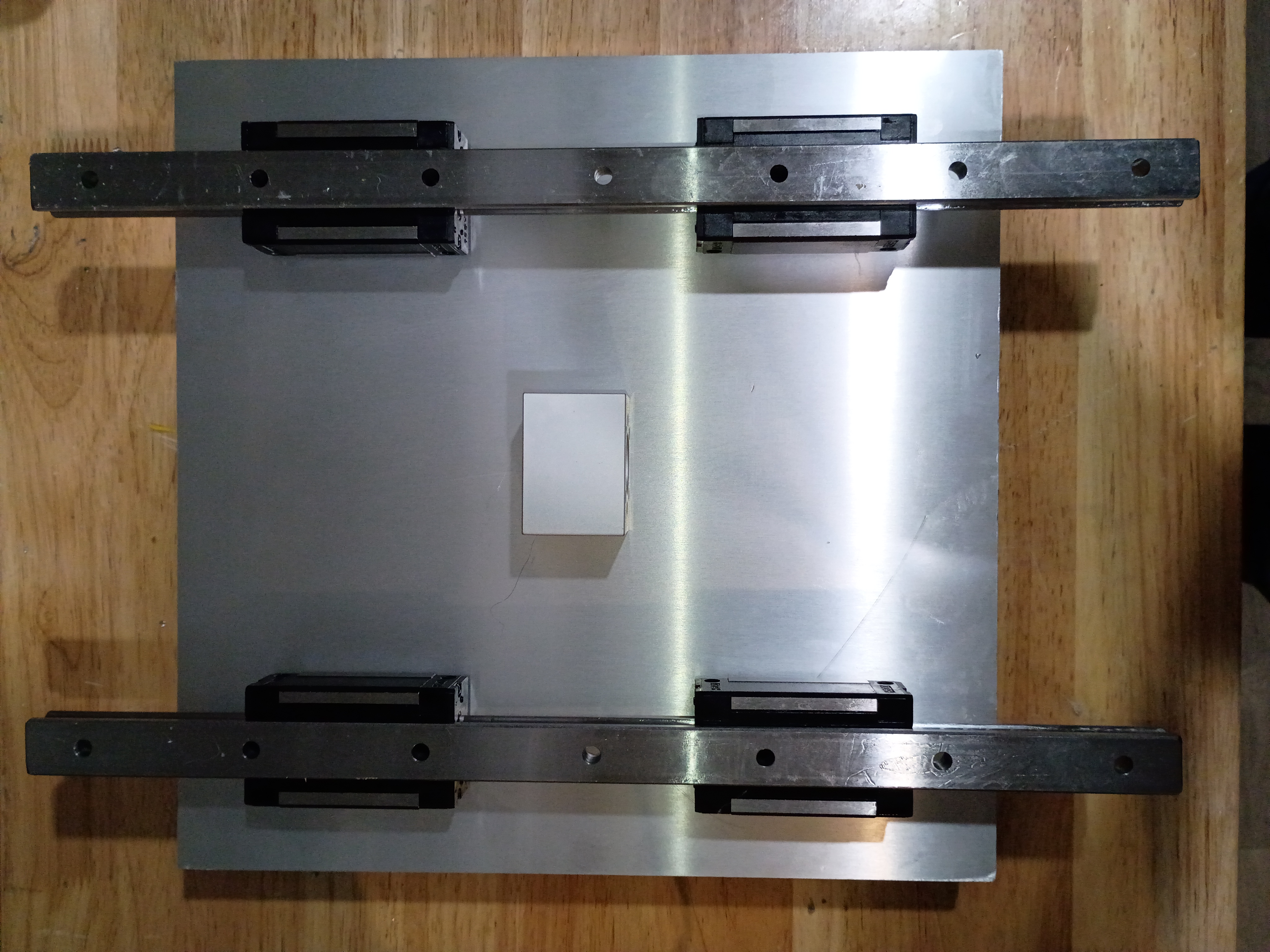
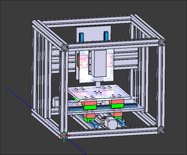
Put final counterbores into X-Y gantry plate and test-fit the linear rails and ballscrew ball nut carriage block. Somehow miraculously everything is aligned. I do still need to put in tapped M5 mounting holes for attaching things. 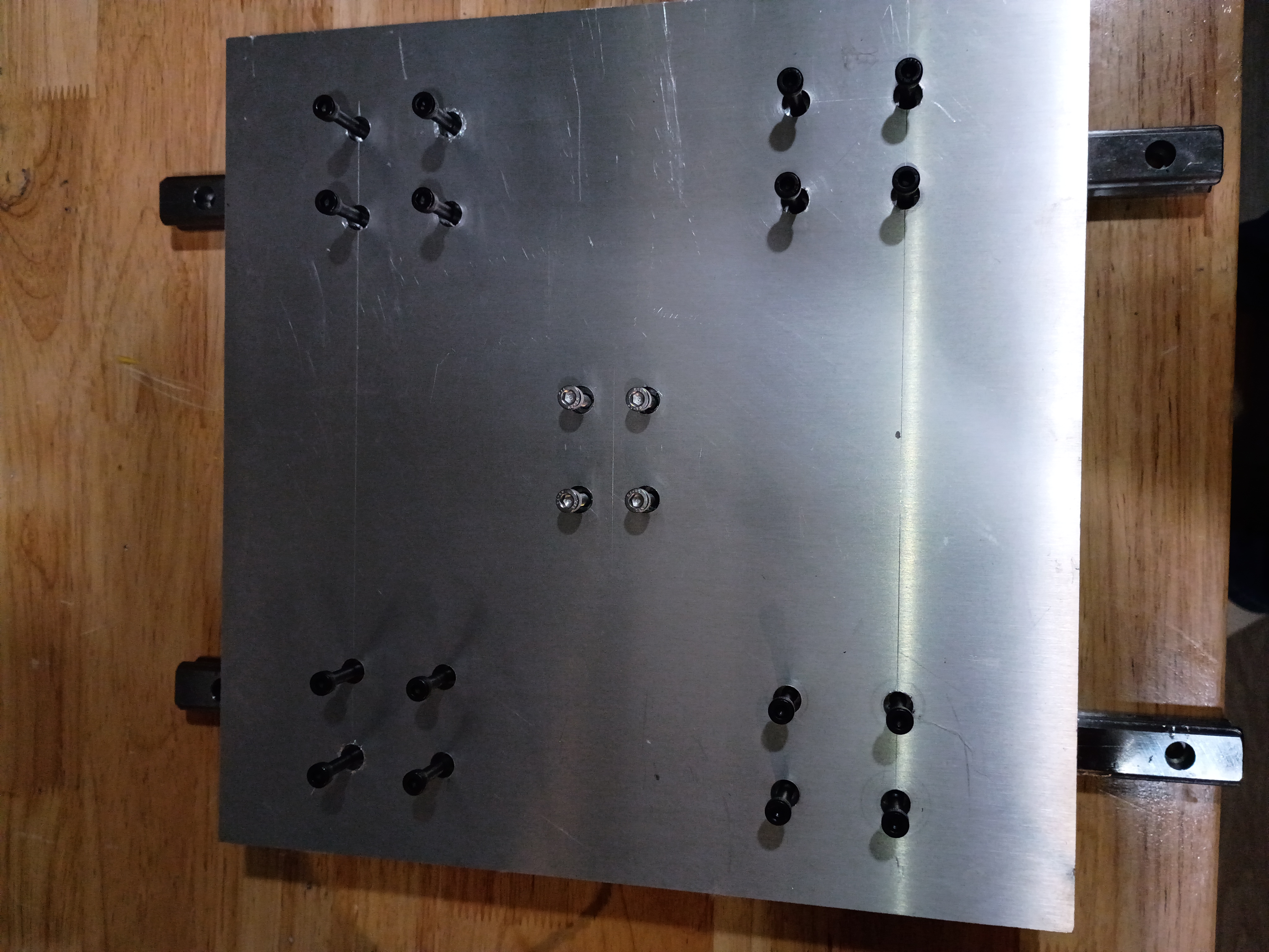
Compiled the full project code from the minimum viable test cases, but I am unable to test it easily until USPS delivers the 7-segment breakout PCBs, which were supposed to be delivered yesterday.
Threw a quick GPS data display together using a Pi Zero (overkill, used only for the USB GPS dongle). It shows lat/long/alt/speed and the fix status and number of satellites observed. 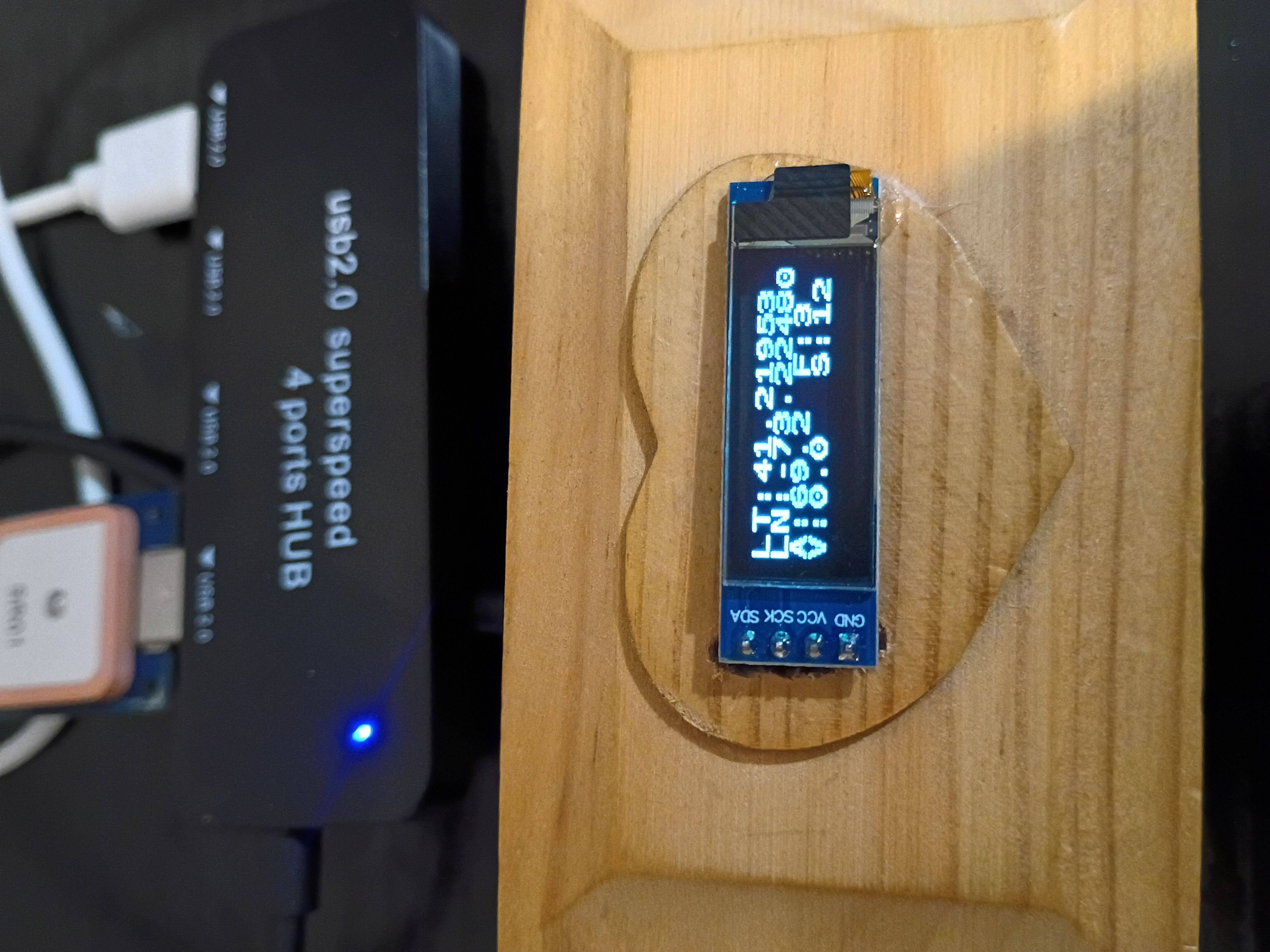
I updated the web journal-generating script to add some additional info and formatting.
Began to drill and counterbore mounting holes for the X-Y gantry plate. These slotting counterbore bits are really nice but get gummed up quickly and stall the motor of my weak drill press. Also have to use a cordless drill to reach the central holes. Would be nice to make a nice drill press. 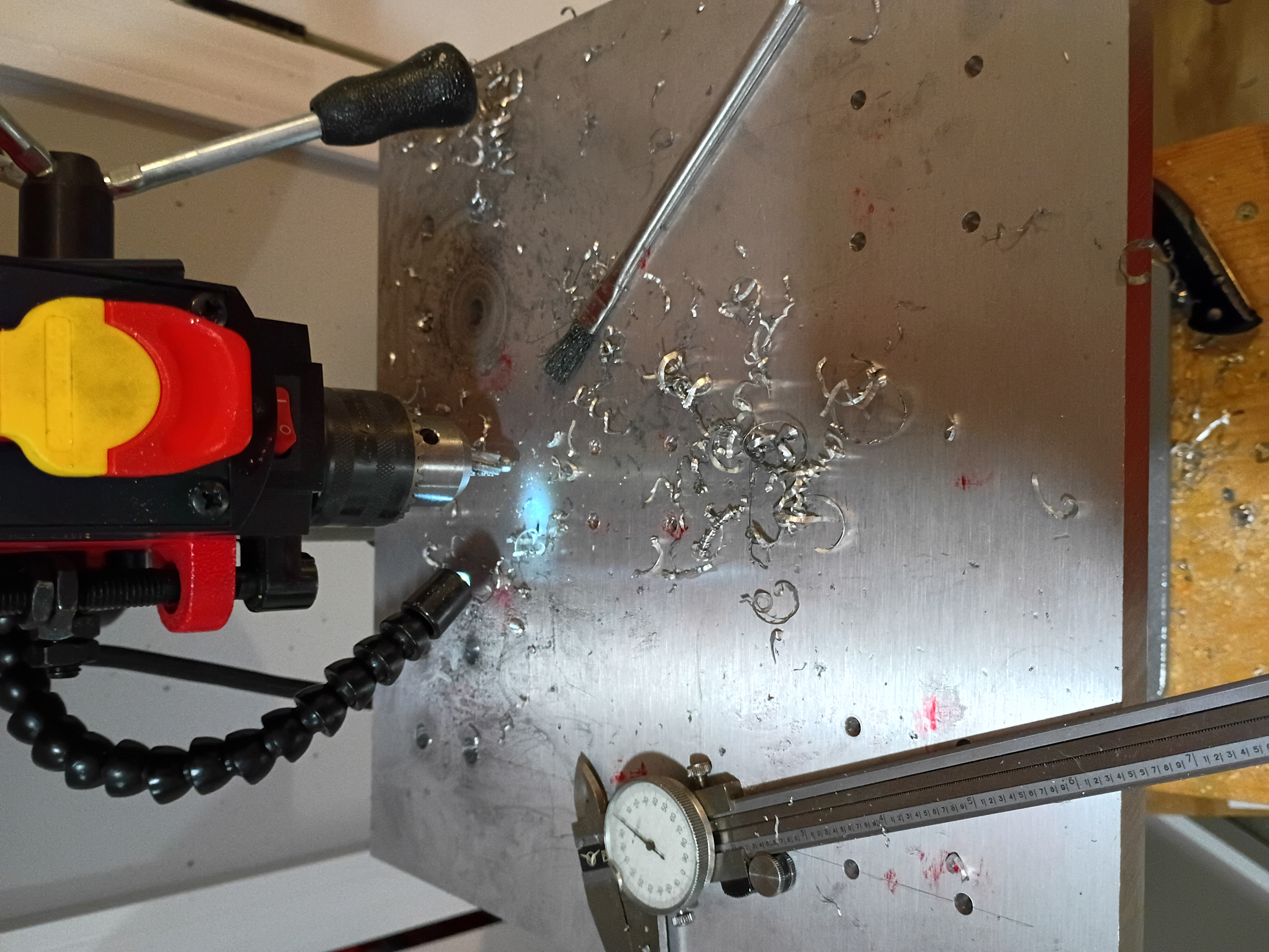
Took inventory of CNC mill project after long hiatus. Updated CAD model to reflect length of installed collet and bit and migrated to organization repository. Marked out the drill and tap locations for the X-Y gantry plate. 
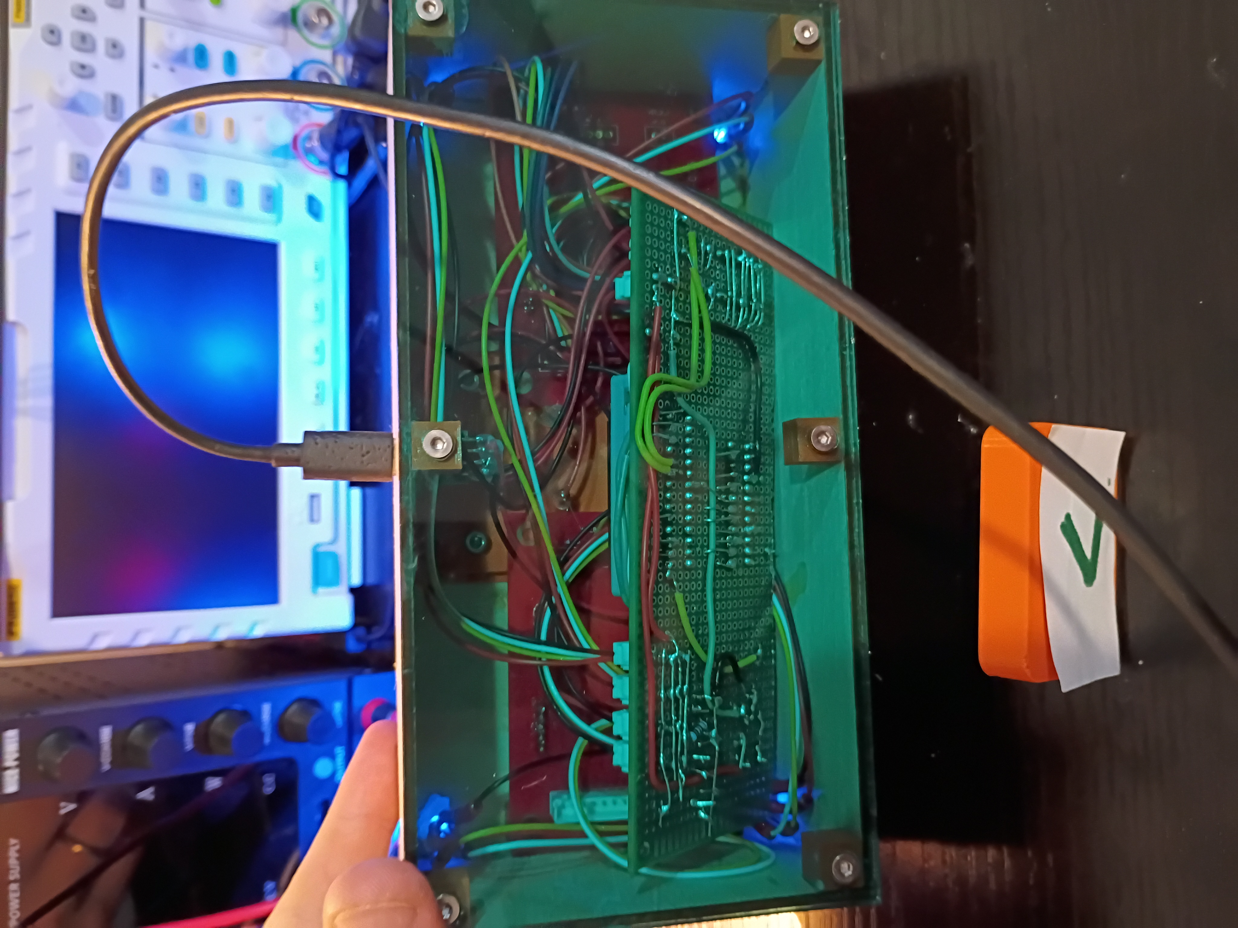
Snipped down main circuitboard to fit snuggly inside the box. Debugged minor soldering issue with one of the RGB LEDs. Wrote this code to control the lights in unison with the buzzer depending on the reed switch status. See video example. 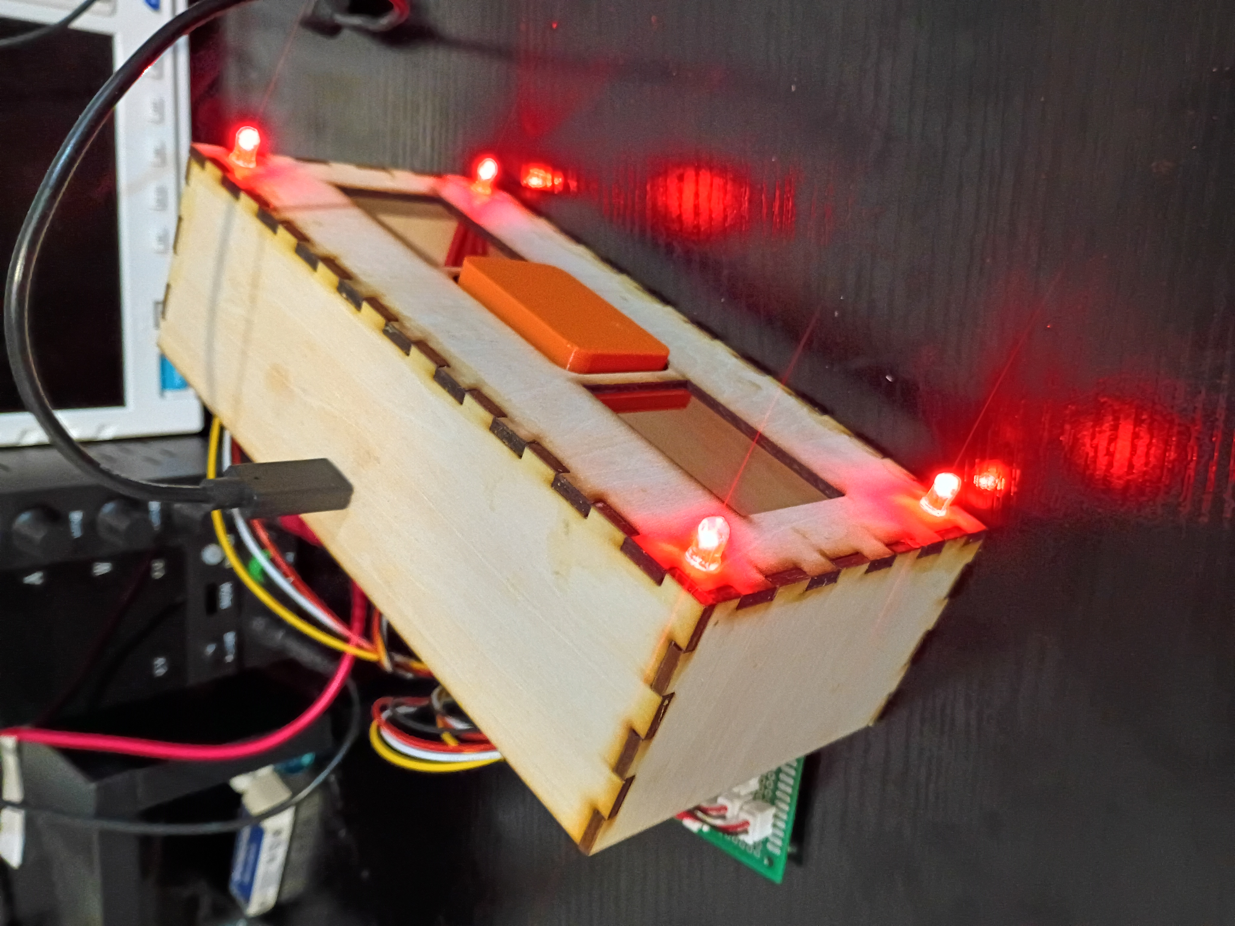
Designed and ordered 6x stepper motor driver PCBs from OSHPark to compare against DKRed. See CAD files. Submission was seamless, and they give better visibility into the order timeline. Pricing is comparable to DKRed. I decided not to expedite. 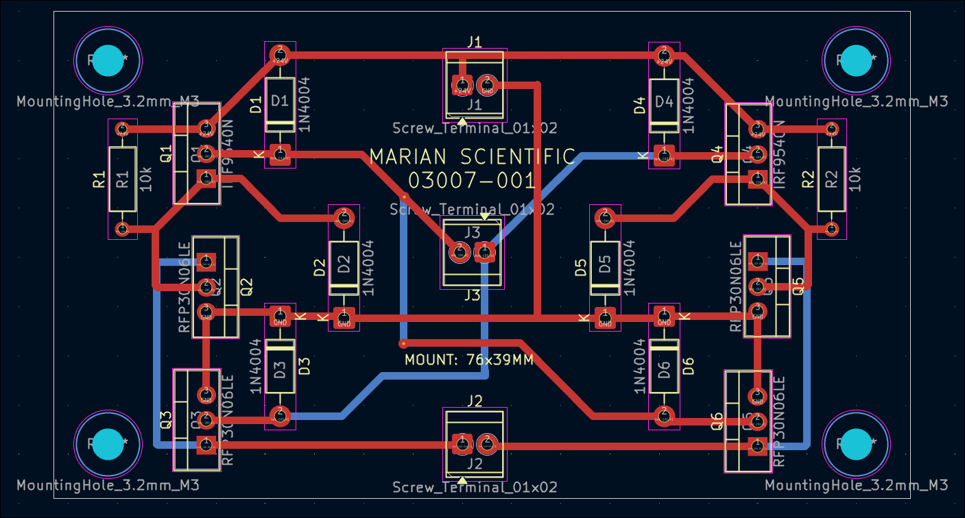
I updated the web journal-generating script to categorize entries by submission month and reorganize the main page by project/author and the most-recent 10 entries. This is to improve page load times. A similar monthwise breakout eventually needs to be done at the author-level as well.
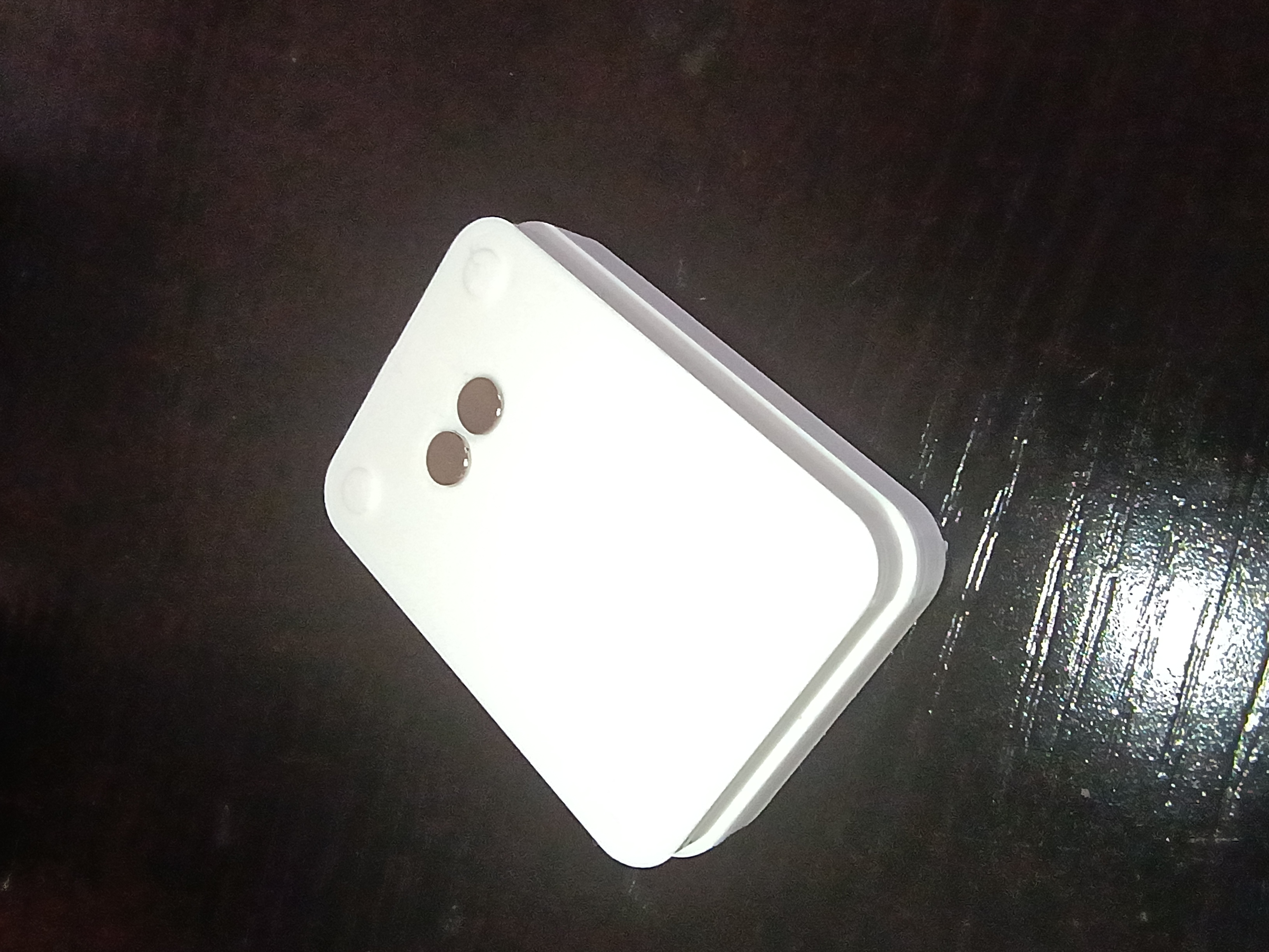
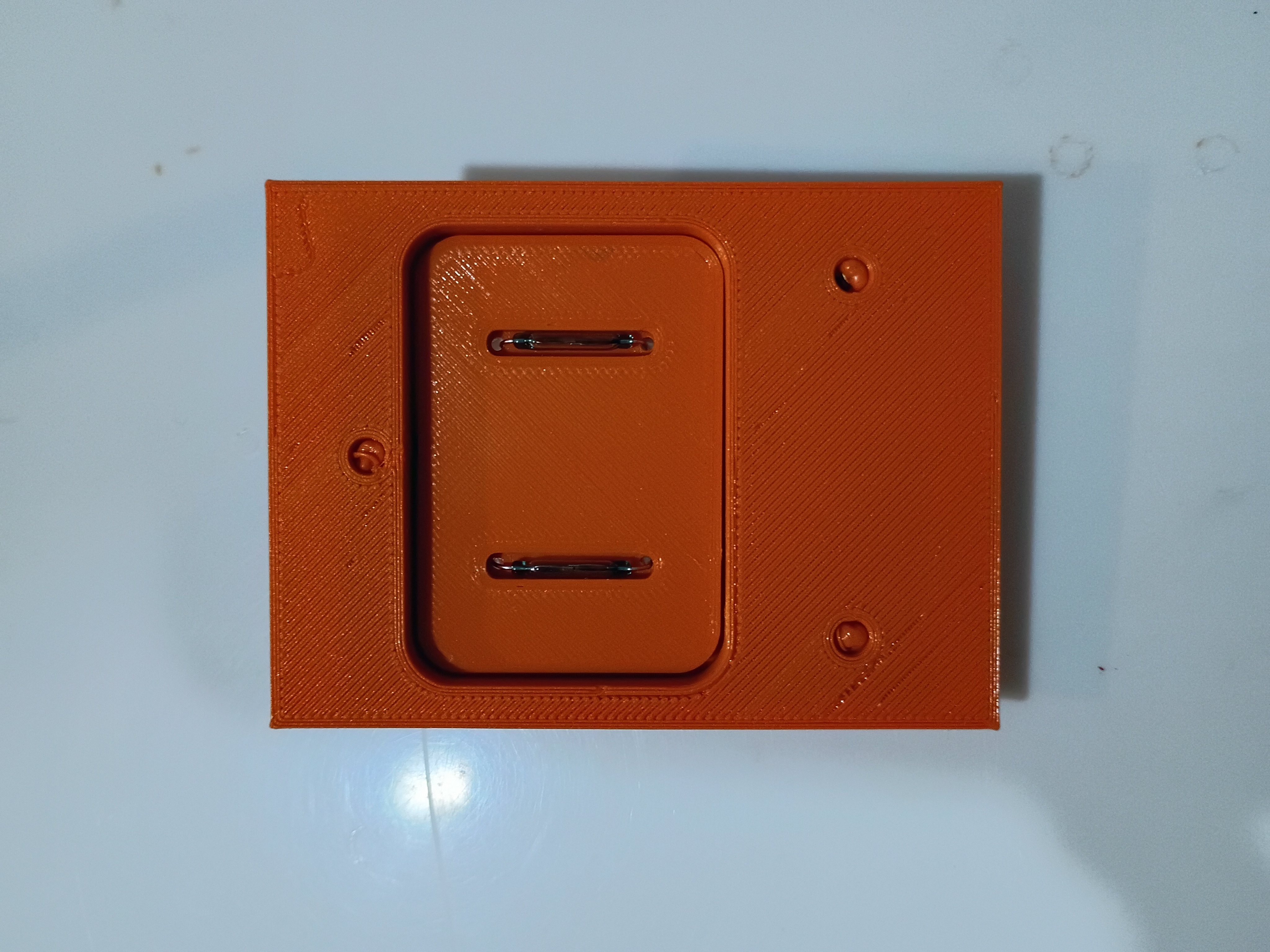
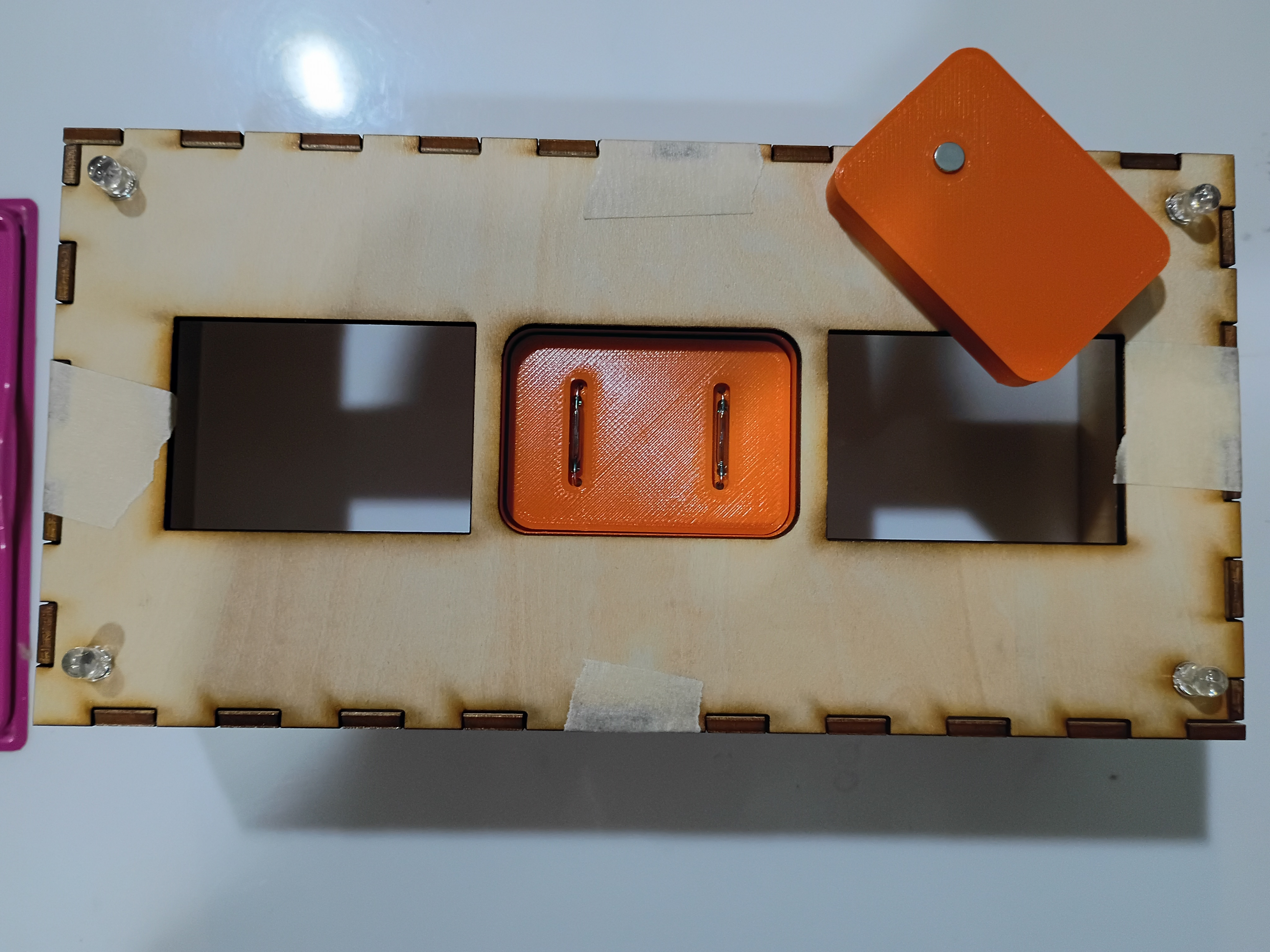
Reprinted magnet block with 2 holes to accept 2 magnets which must be oriented with opposite polarity facing out for best detection by the reed switches. See example. Also glued mounting blocks for the bottom acrylic plate. 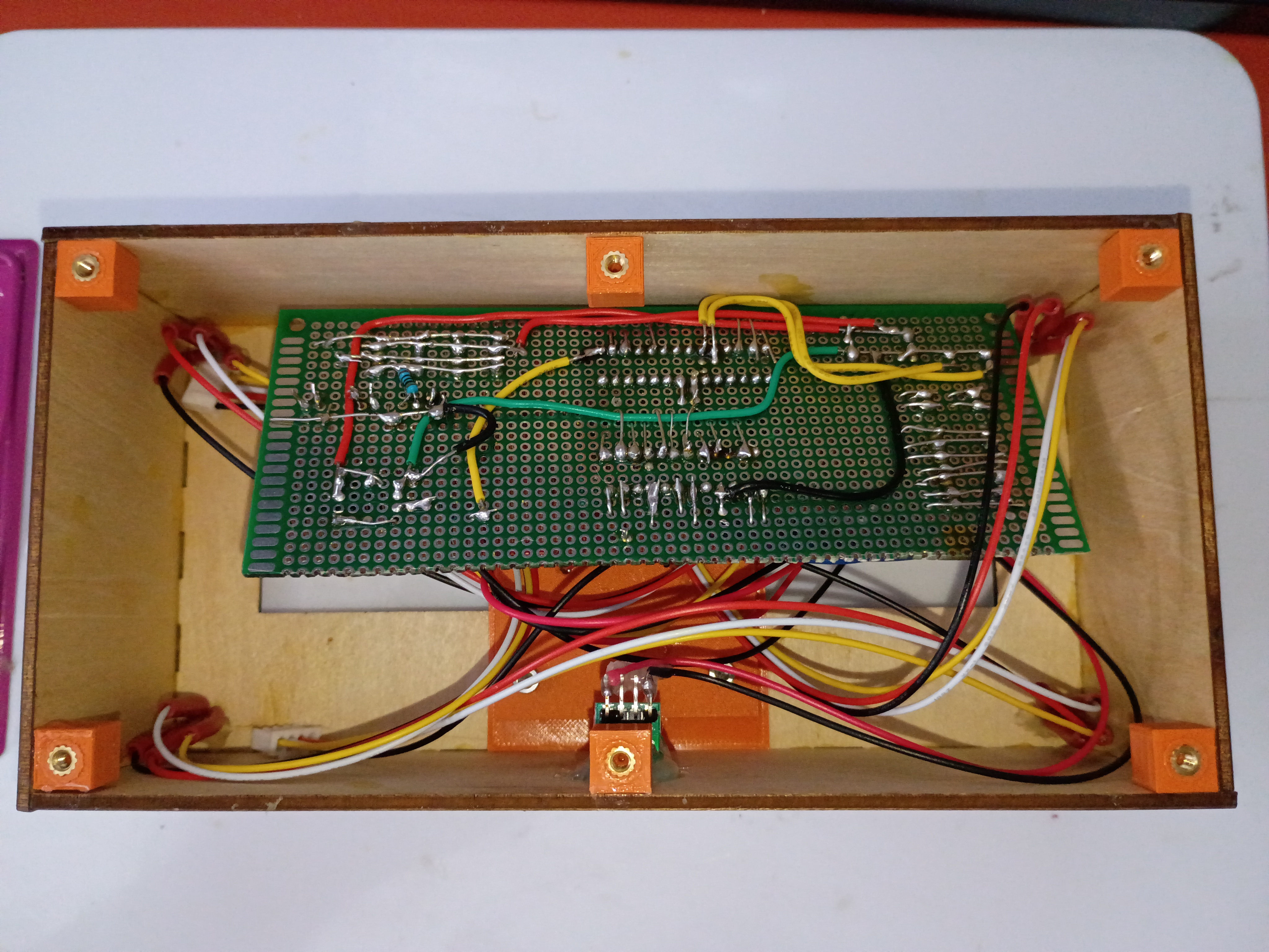
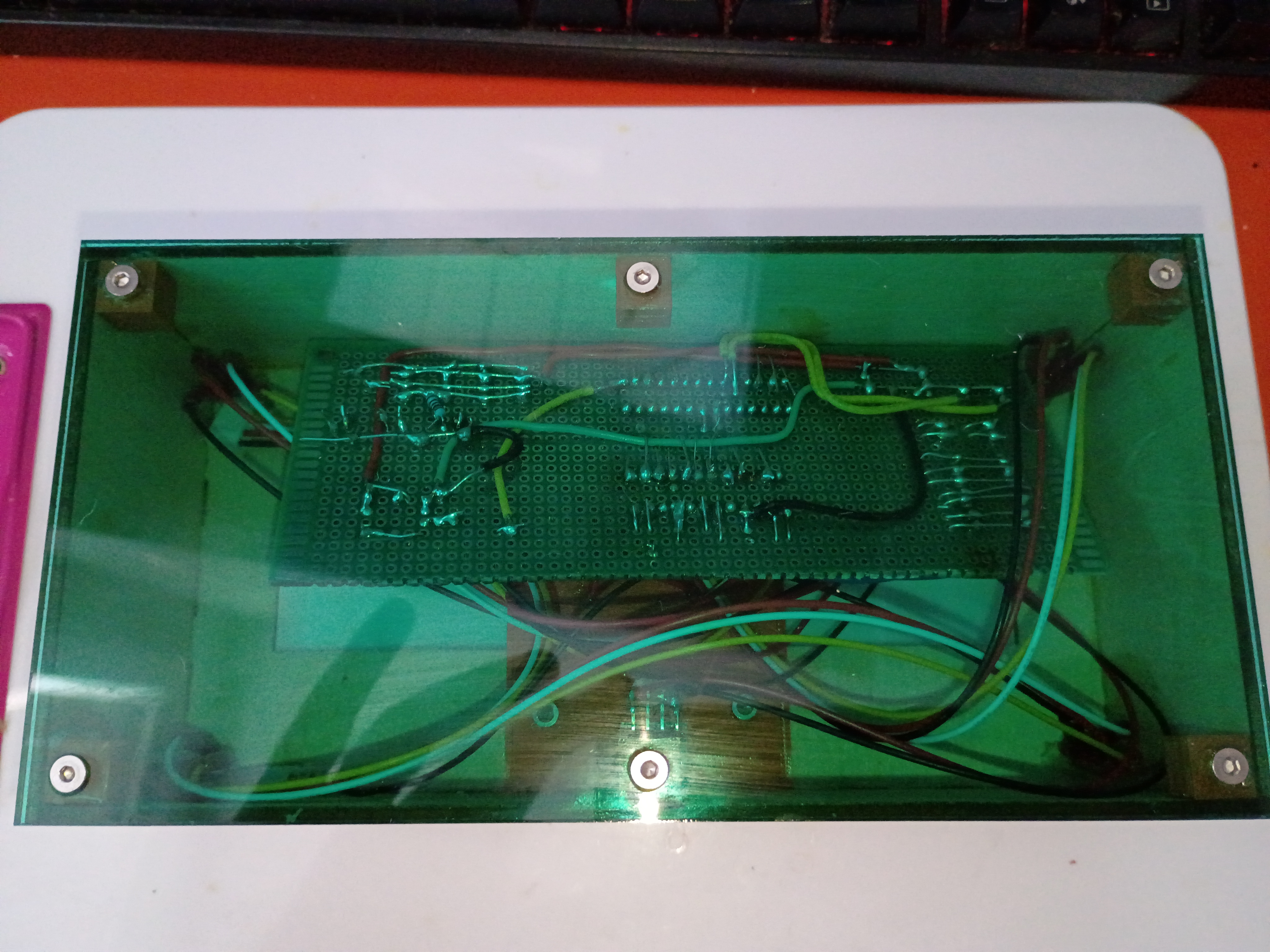
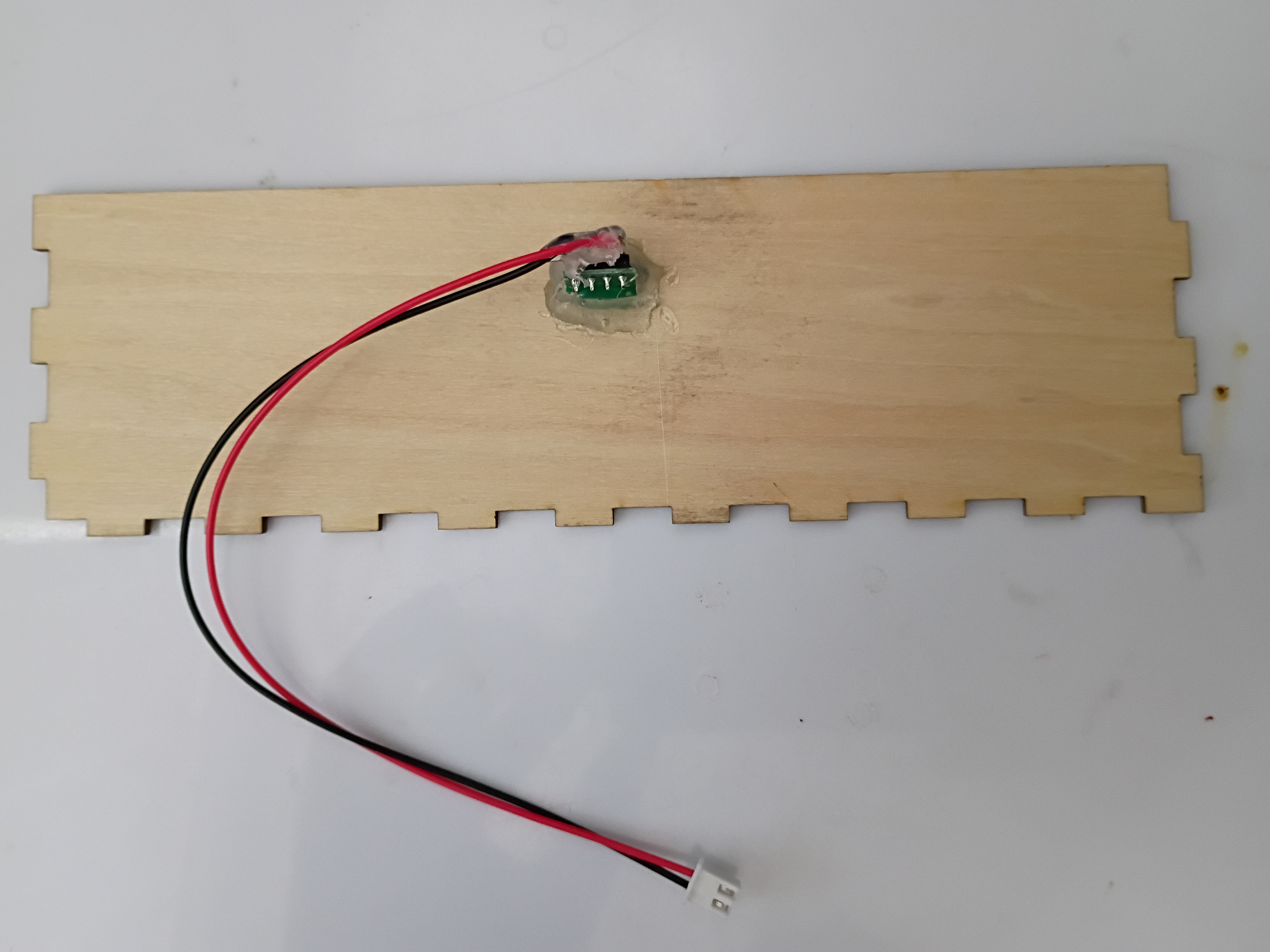
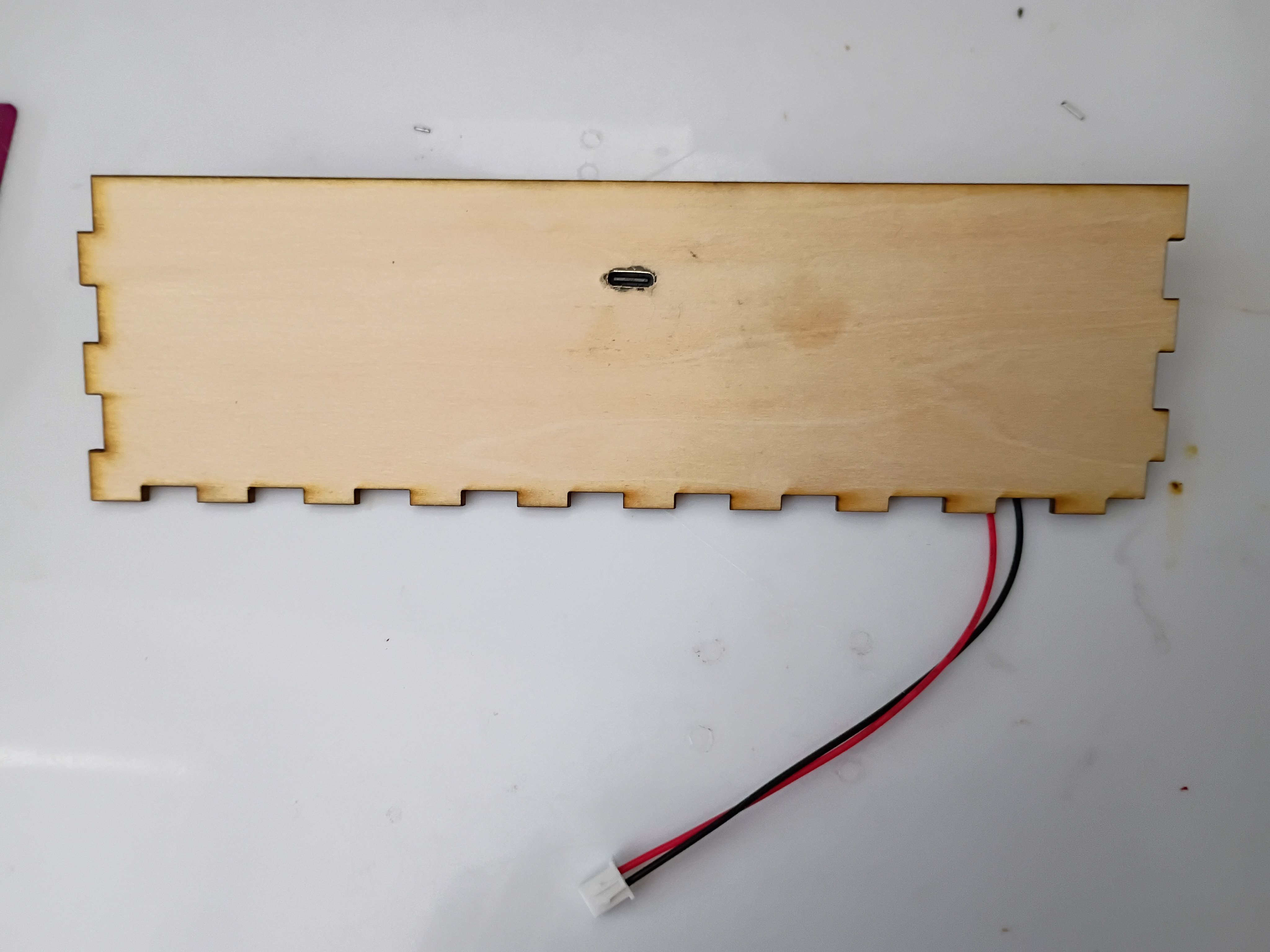
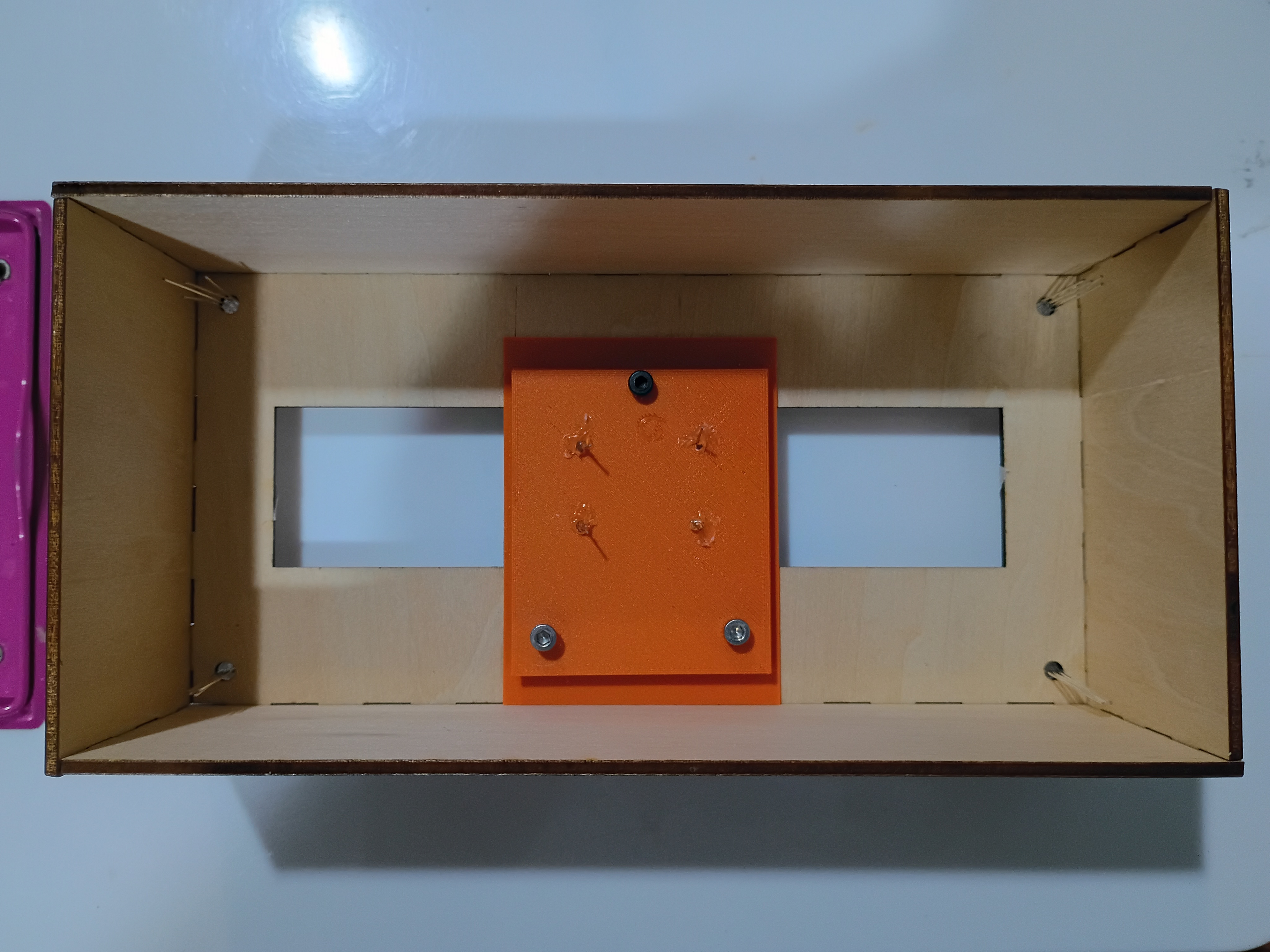
Drilled slot in box and mounted USB-C connector. Mounted, soldered, and heat-shrunk leads to all indicator LEDs and reed switches. Soldered additional JST sockets for the reed switches onto the main circuitboard. Glued box together. Tested magnetic field detection with this C code. 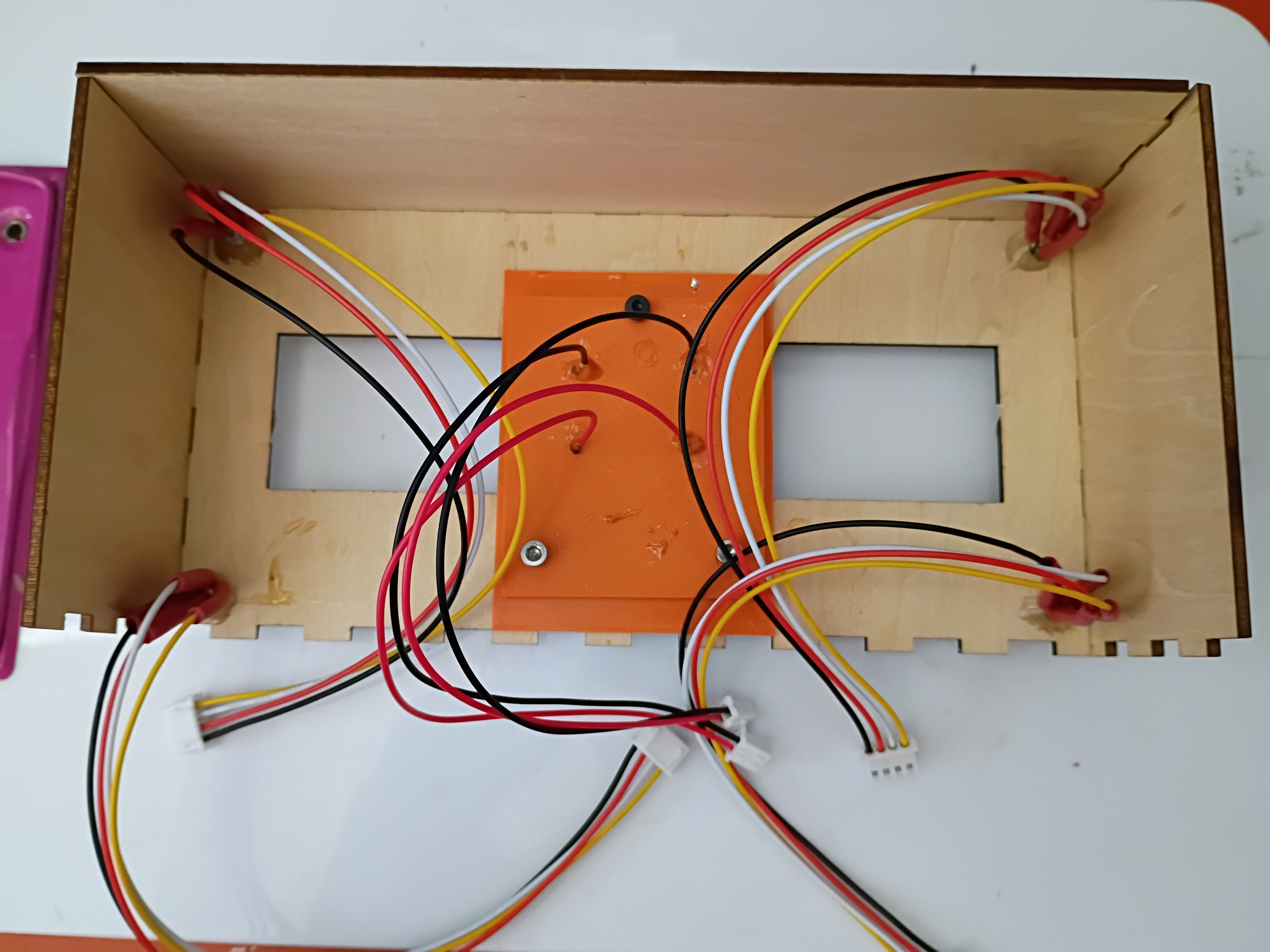
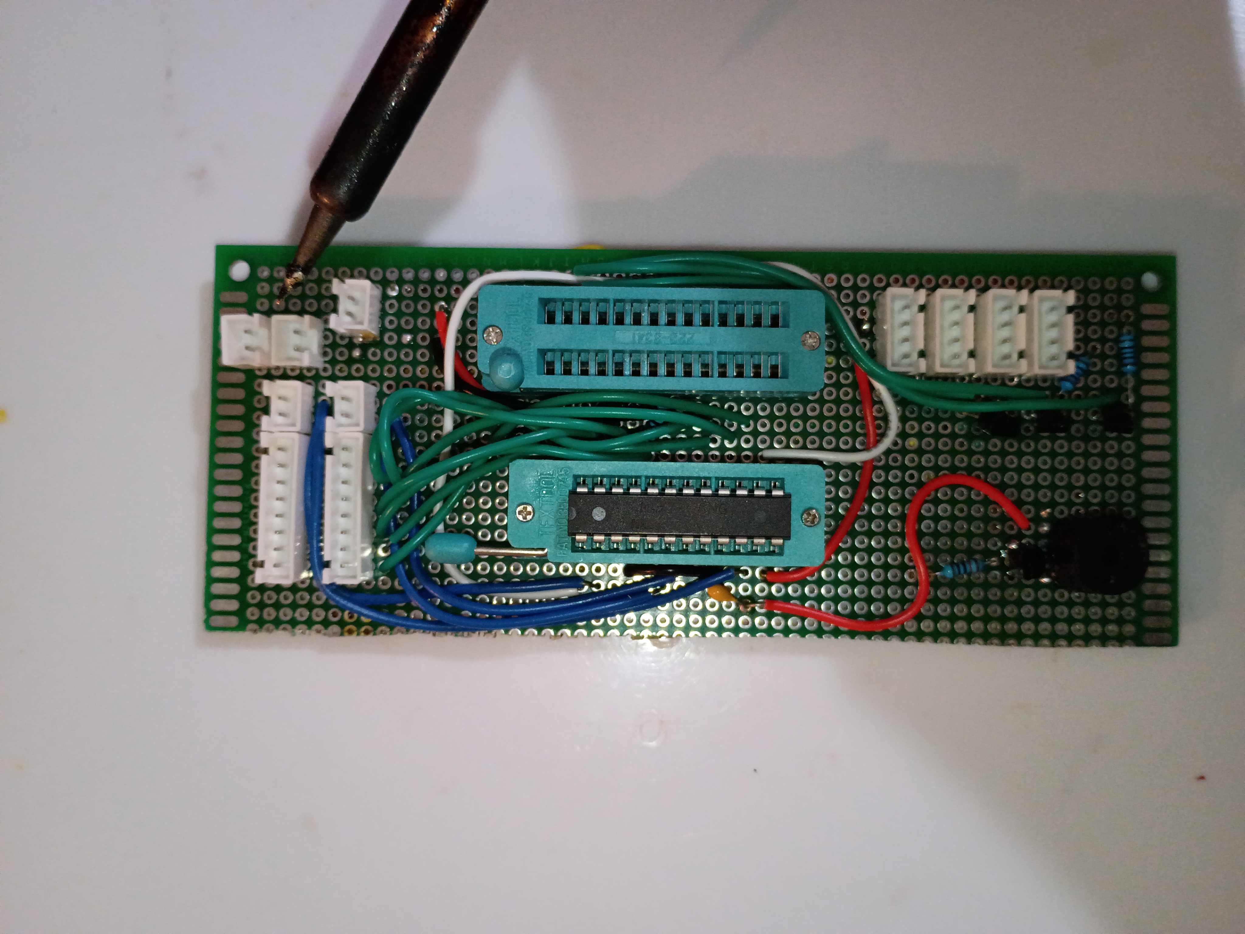
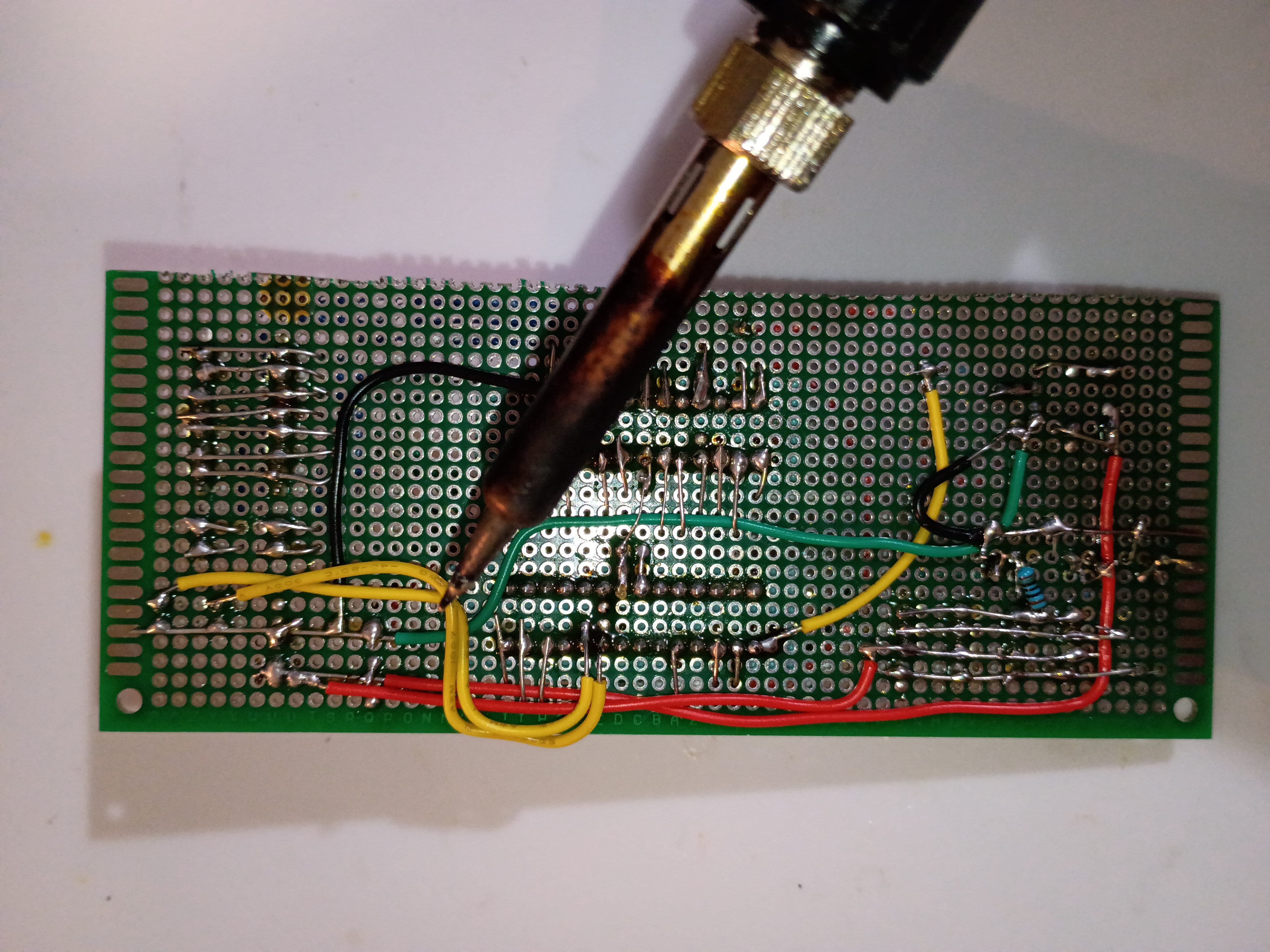
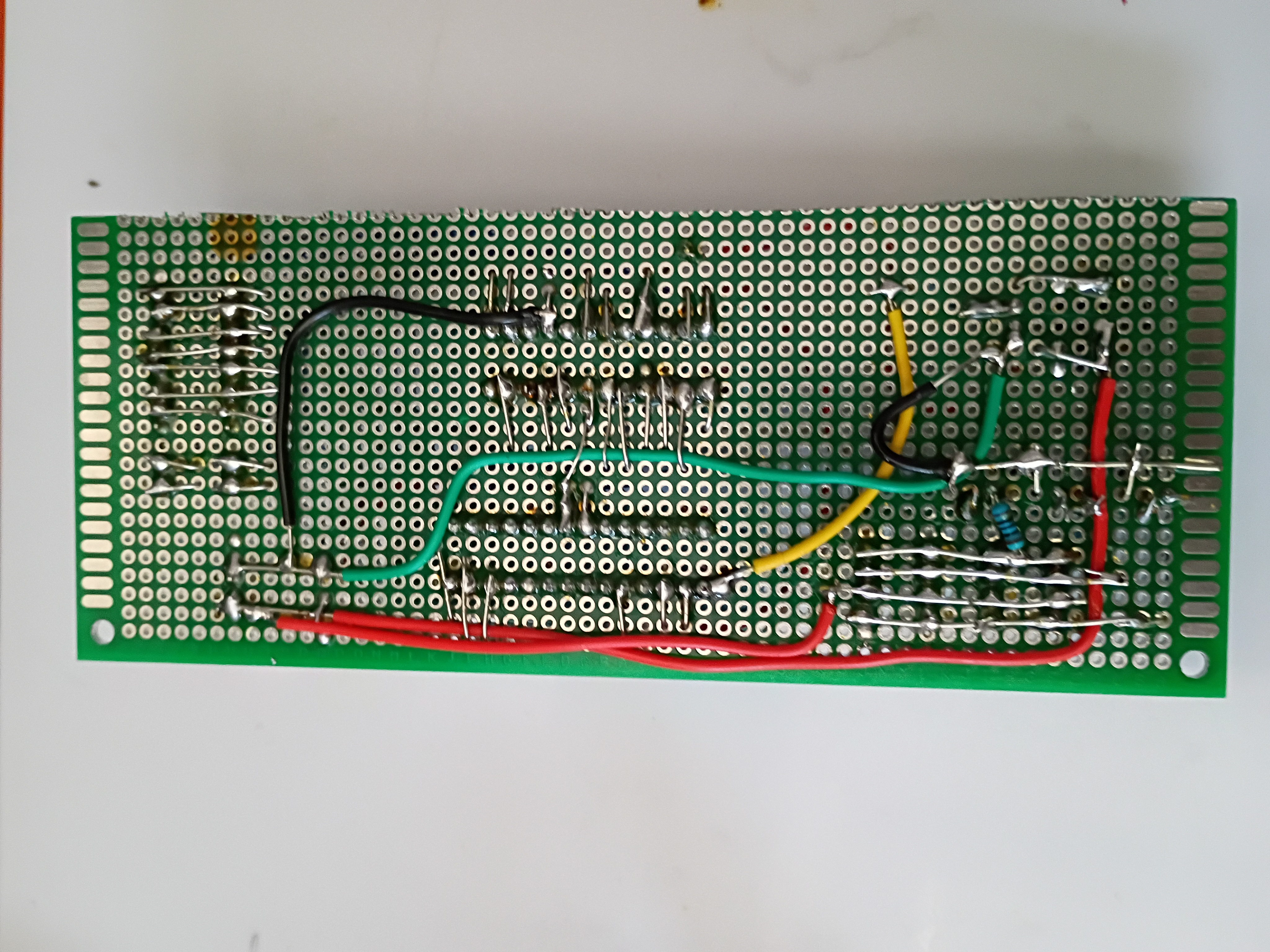
Finished soldering components onto main perfboard. 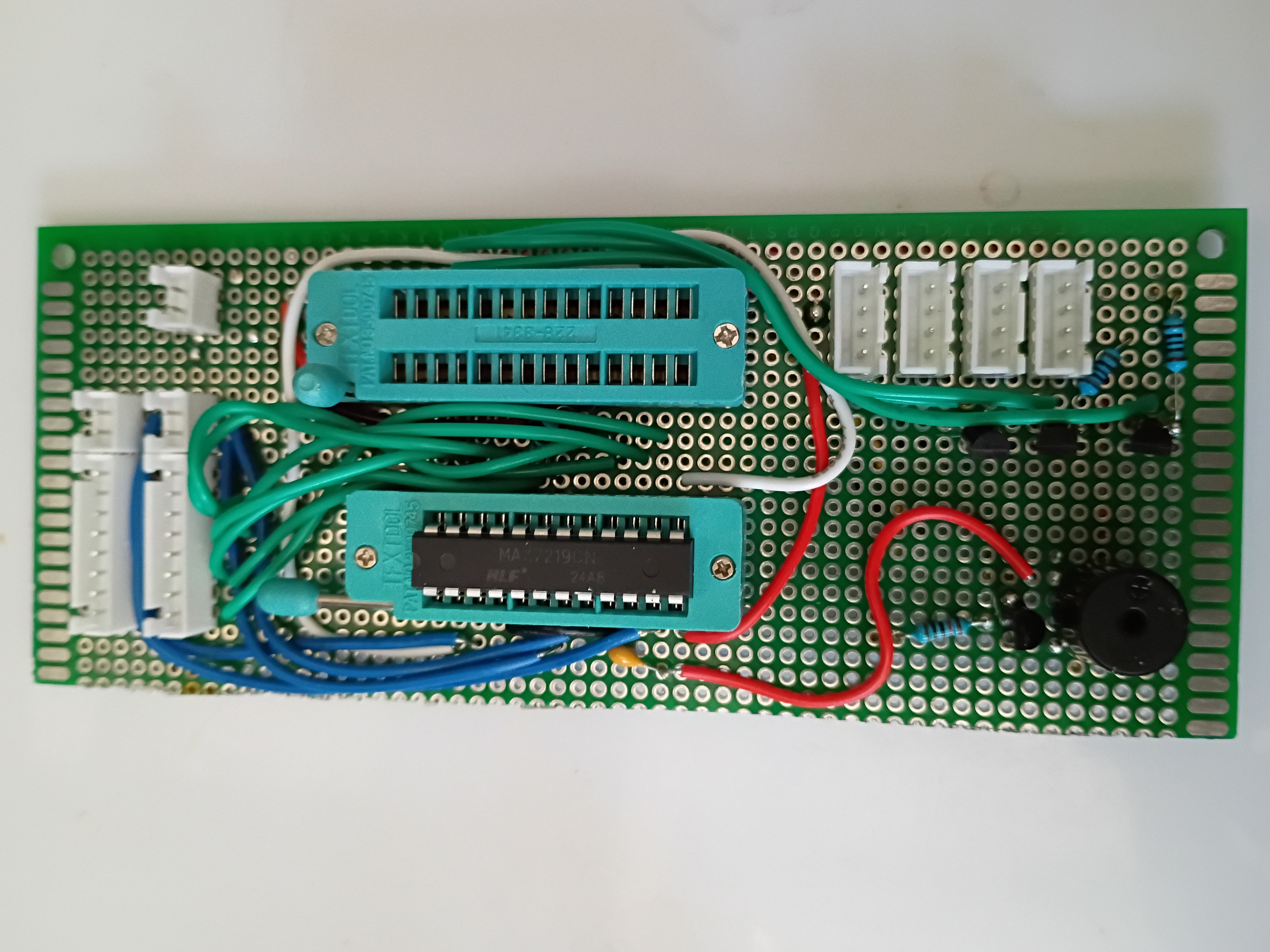
Circuit and code to blink multiple RGB LEDs in unison using 2N7000 mosfets since they draw slightly too much current to be driven by GPIO directly. 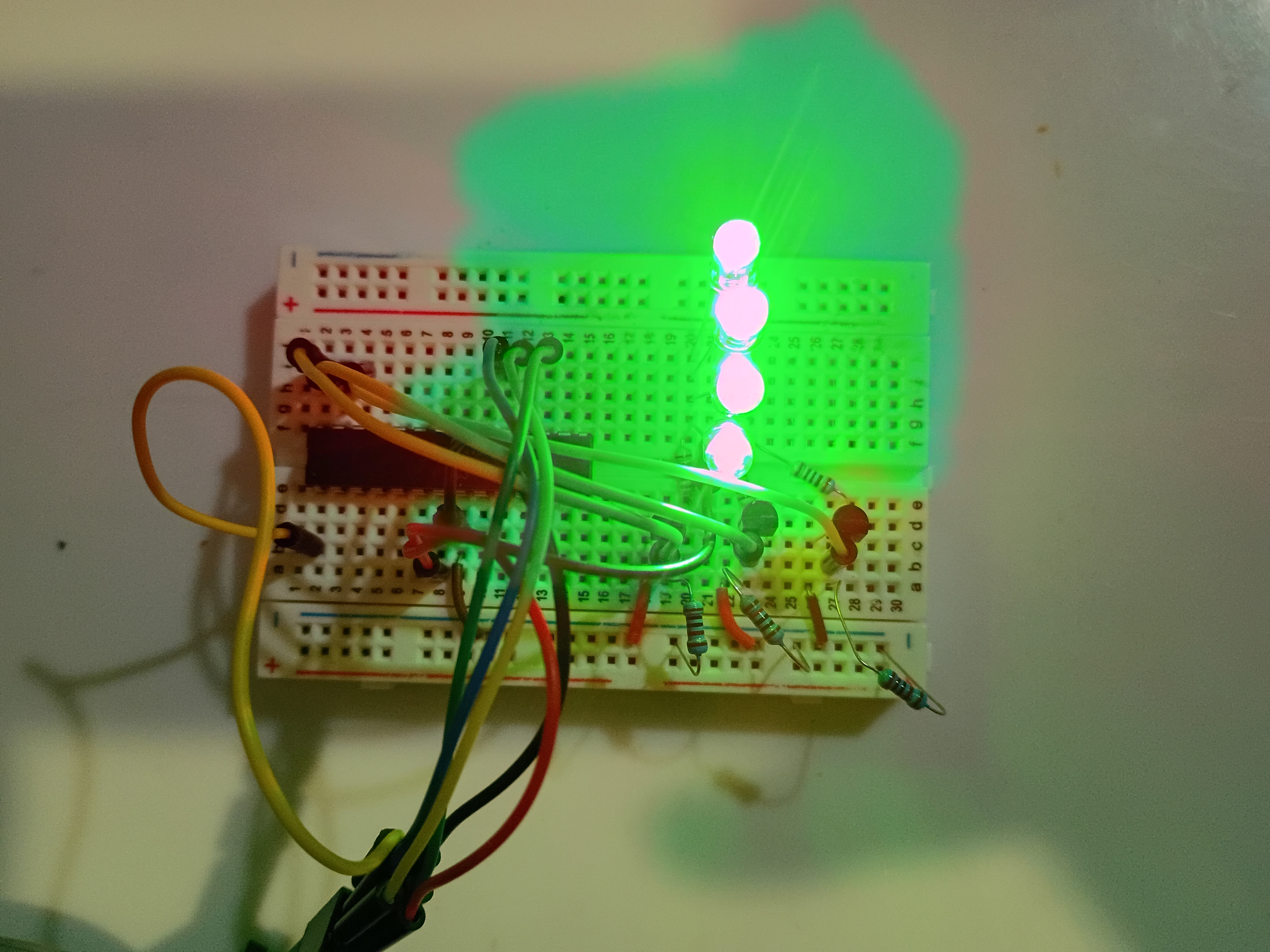
Printed several gear components. Manufacturing recommendation is to make the hole in the hour drive gear all the way thru the part and increase the inner diameter slightly (0.1mm) for better clearance with the minute shaft. Components were assembled and functionality was tested successfully. 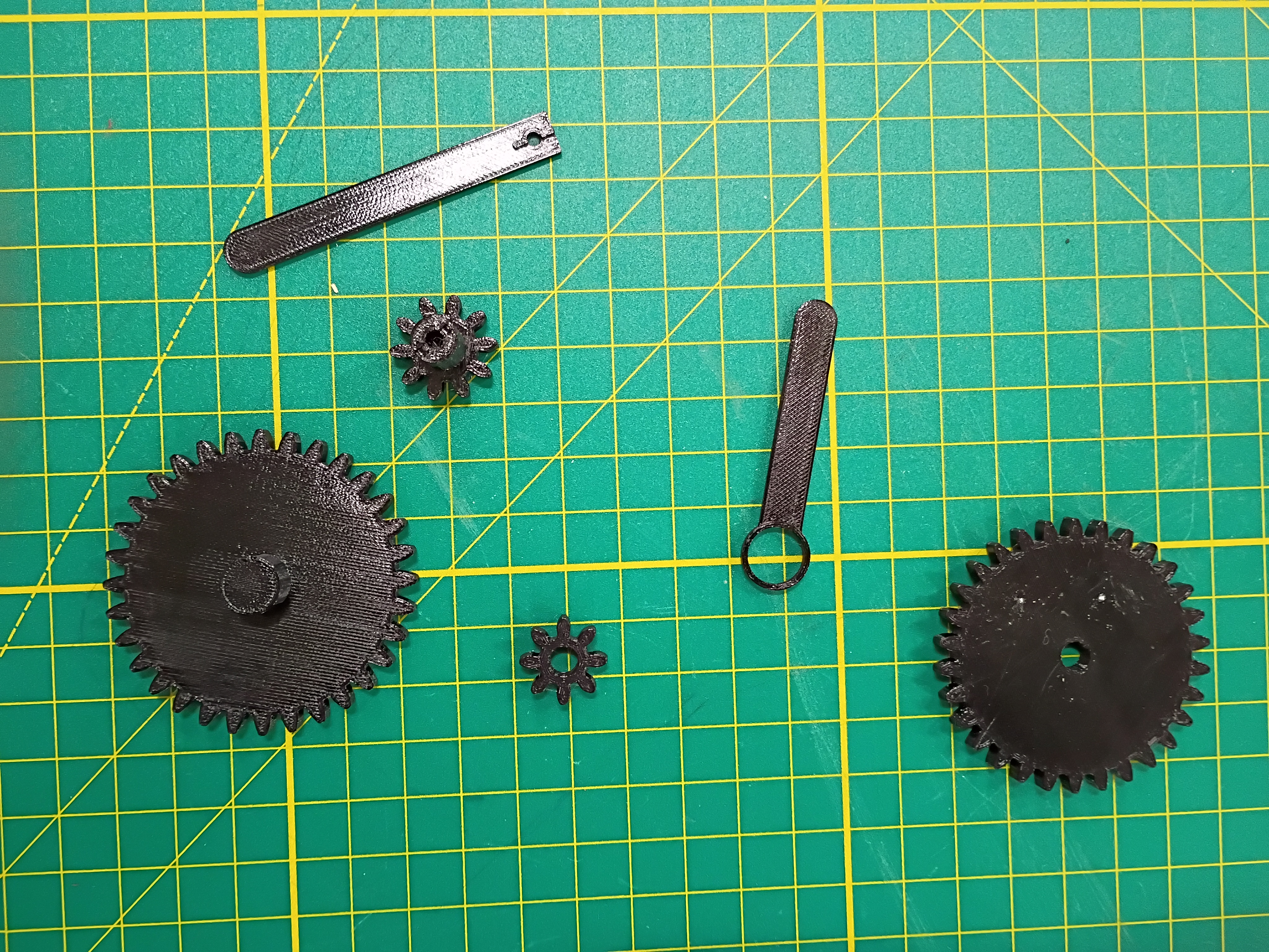
Laser cut 3mm acrylic bottom panel (30% speed, 100% power/current, 45W, only slightly caught fire). Countersunk holes for M3 screws (tendency to shatter, will not do again). Did a dry fit with the rest of the box. Continued to solder more components. 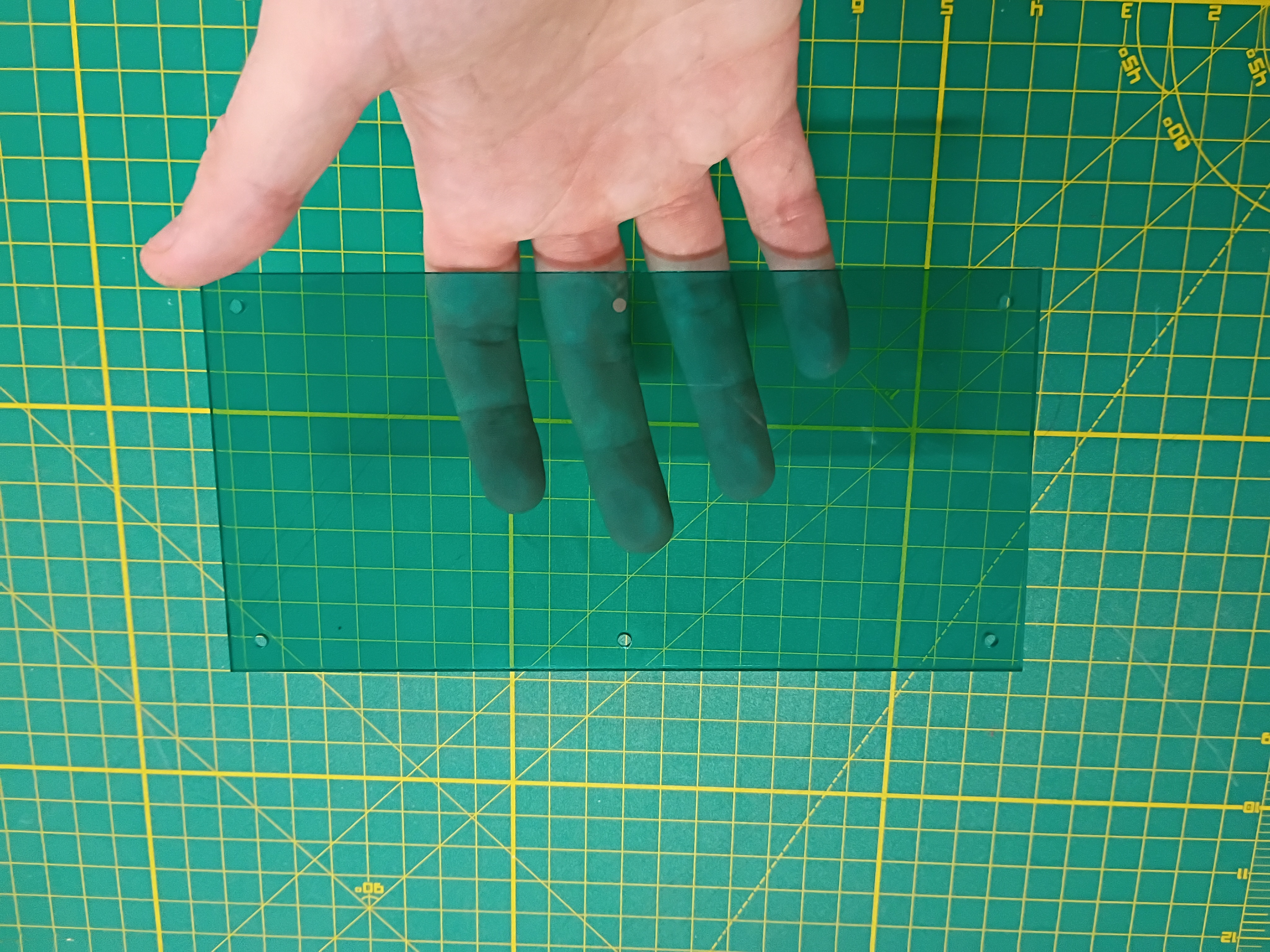
Cut perfboard with hacksaw and soldered several components. 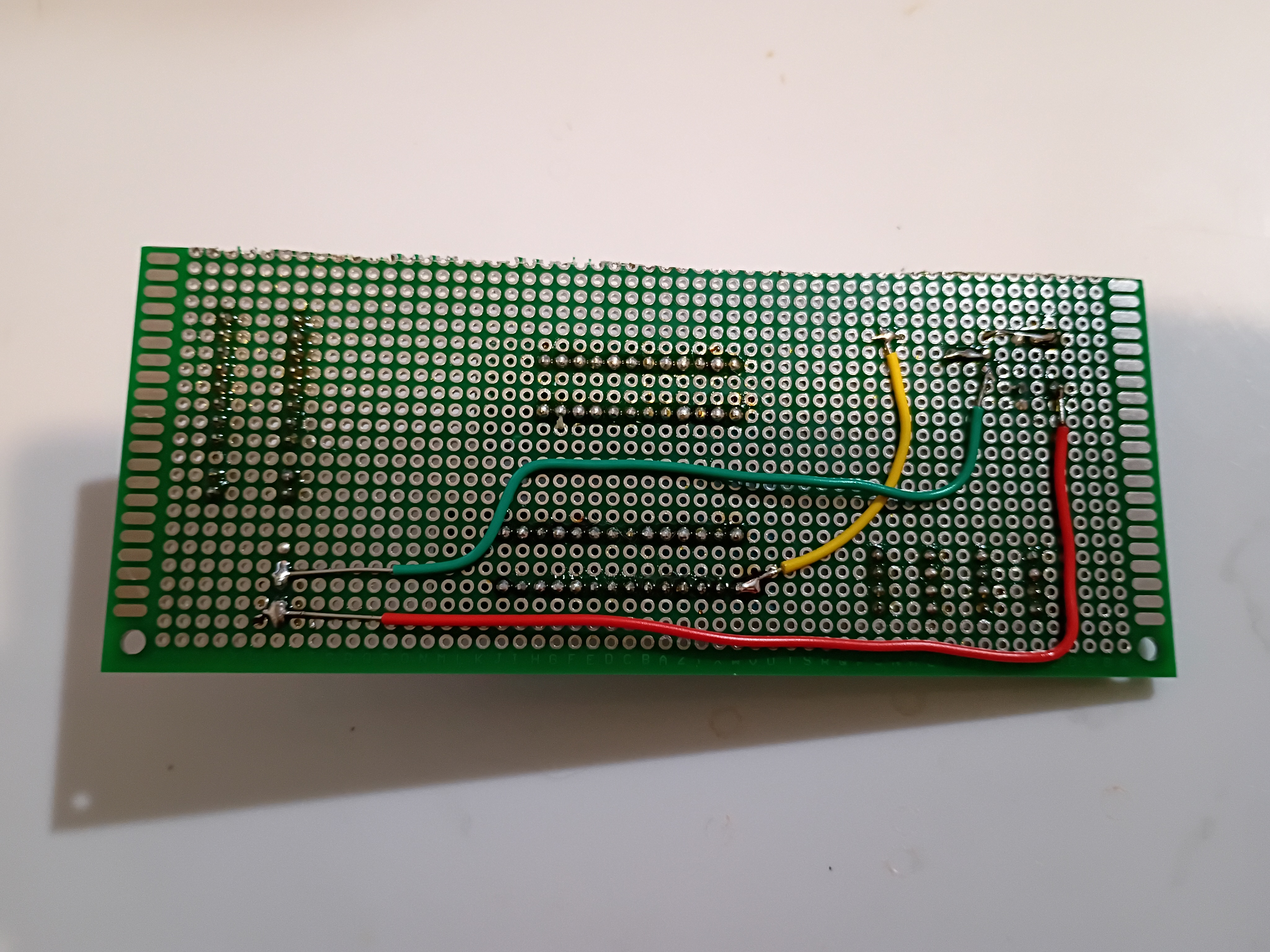
Got buzzer jingles and random integers working on Atmega328P using this C code to scare my cat.
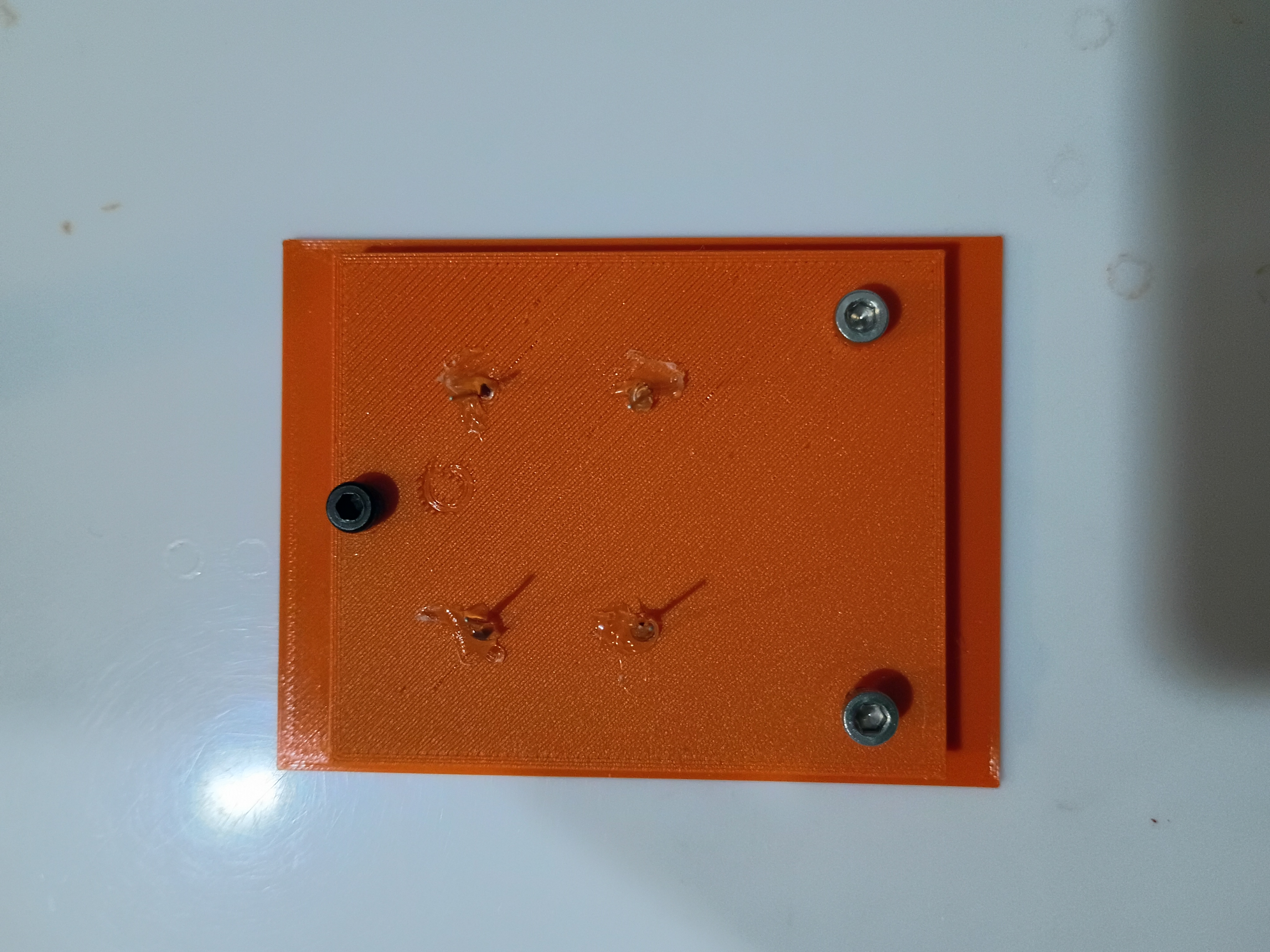
Printed additional mounting components and installed M3x4x5 heat-set inserts. One trick is to set them 75% in and then flip the part over and press it into the table; that gives the best surface finish. Installed reed switches and central chassis onto underside of box surface. Installed small magnet into plastic block for testing purposes only. 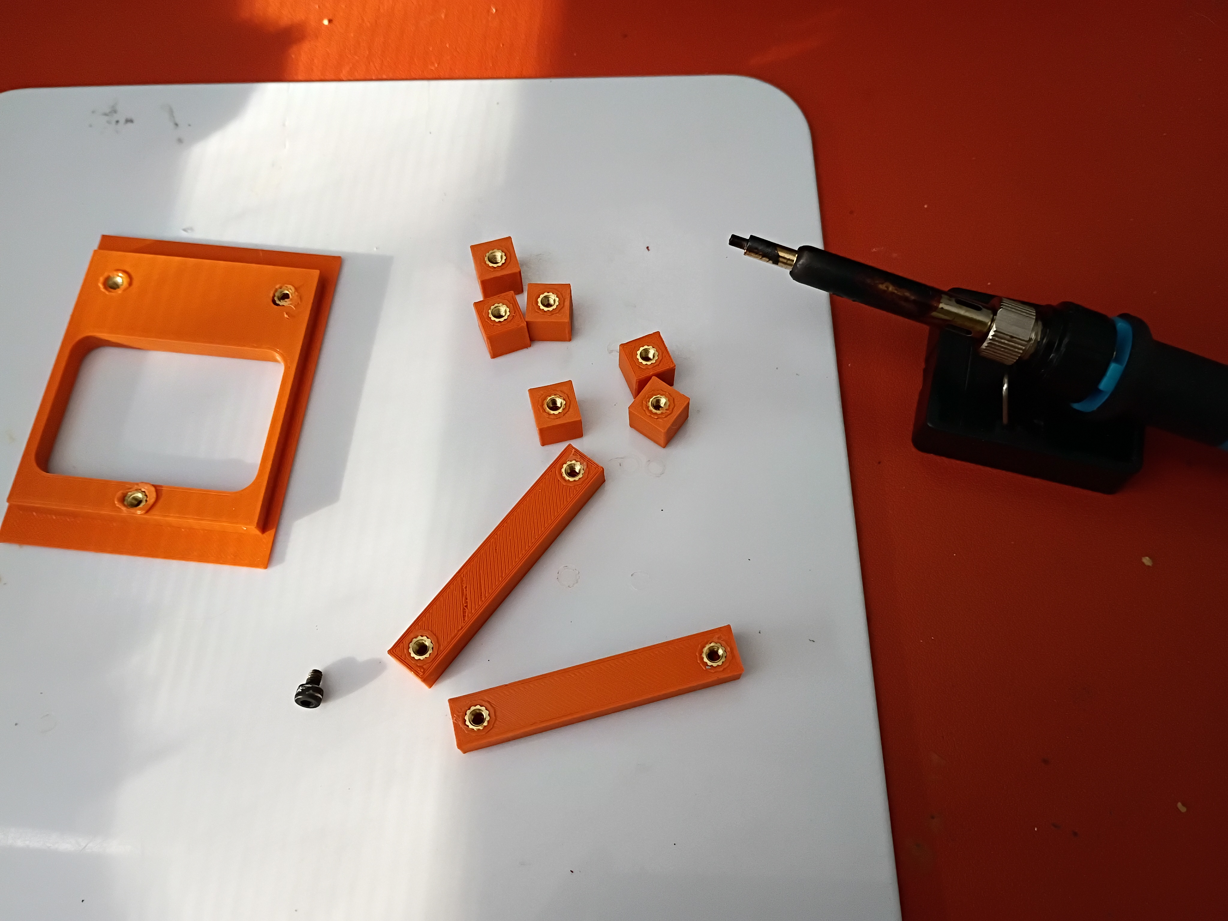
Continued to model assembly and began printing mounting components. 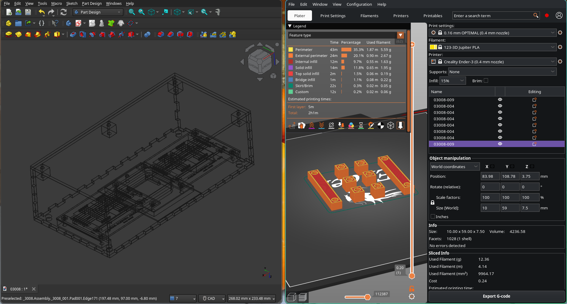
Mocked up removable reed switch holder and partial PCB support assembly. 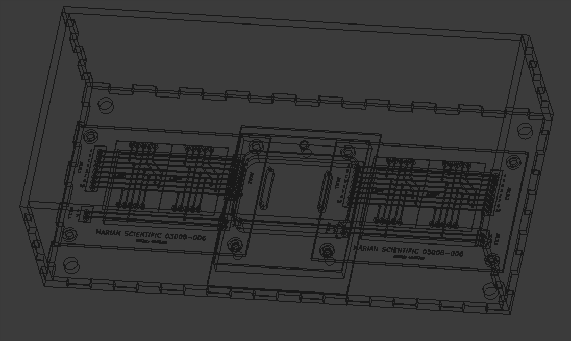
Several plywood panels were laser cut. 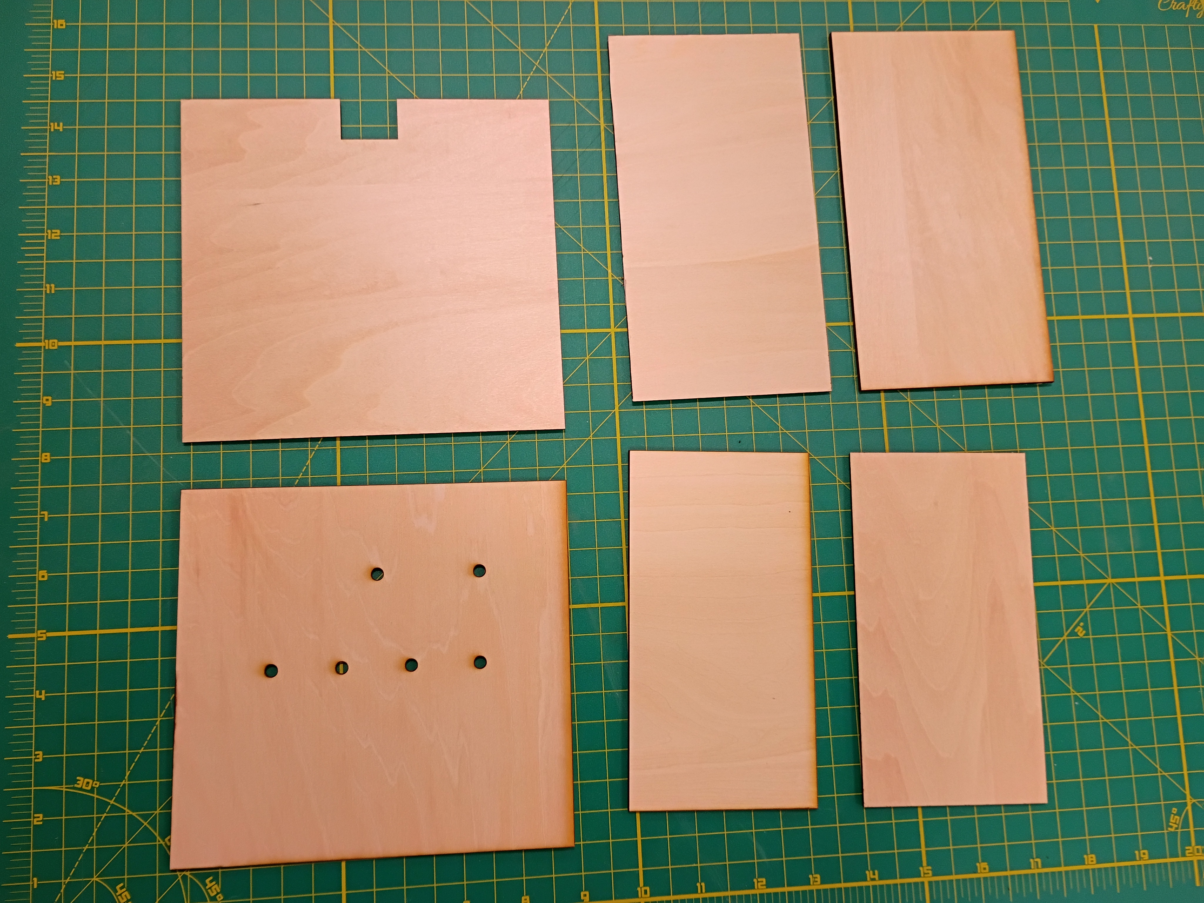
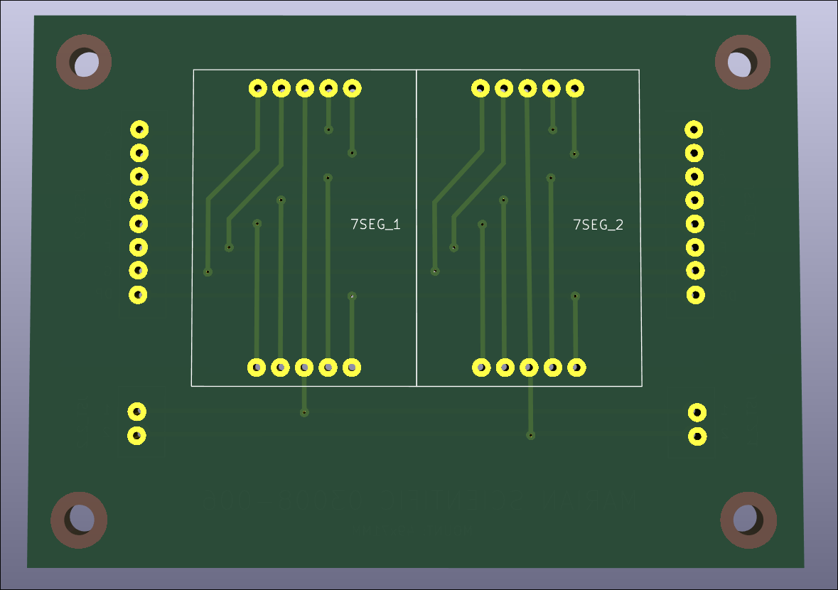
Designed (KiCad) and ordered PCBs (DKRed) to break out sets of 2x 7-segment displays to JST connectors. Cost per board was 11 dollars shipped, made in USA, to arrive in 10 days. Price seems mostly to do with board size. Decided not to expedite the shipping. 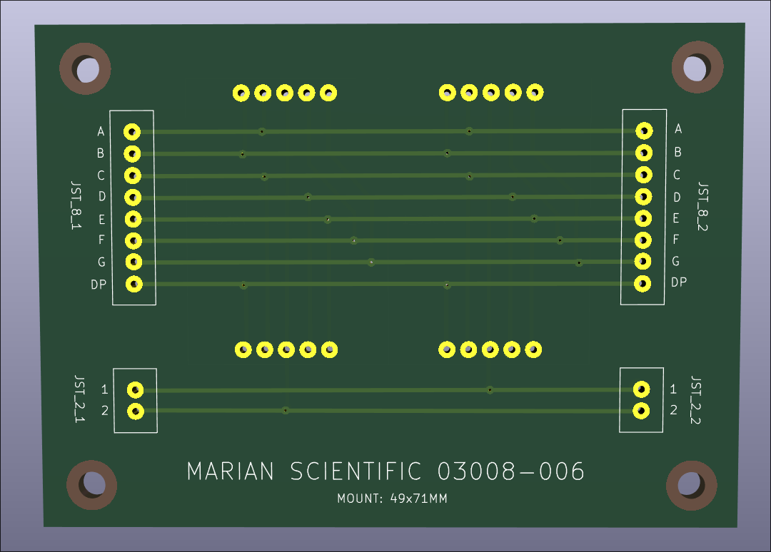
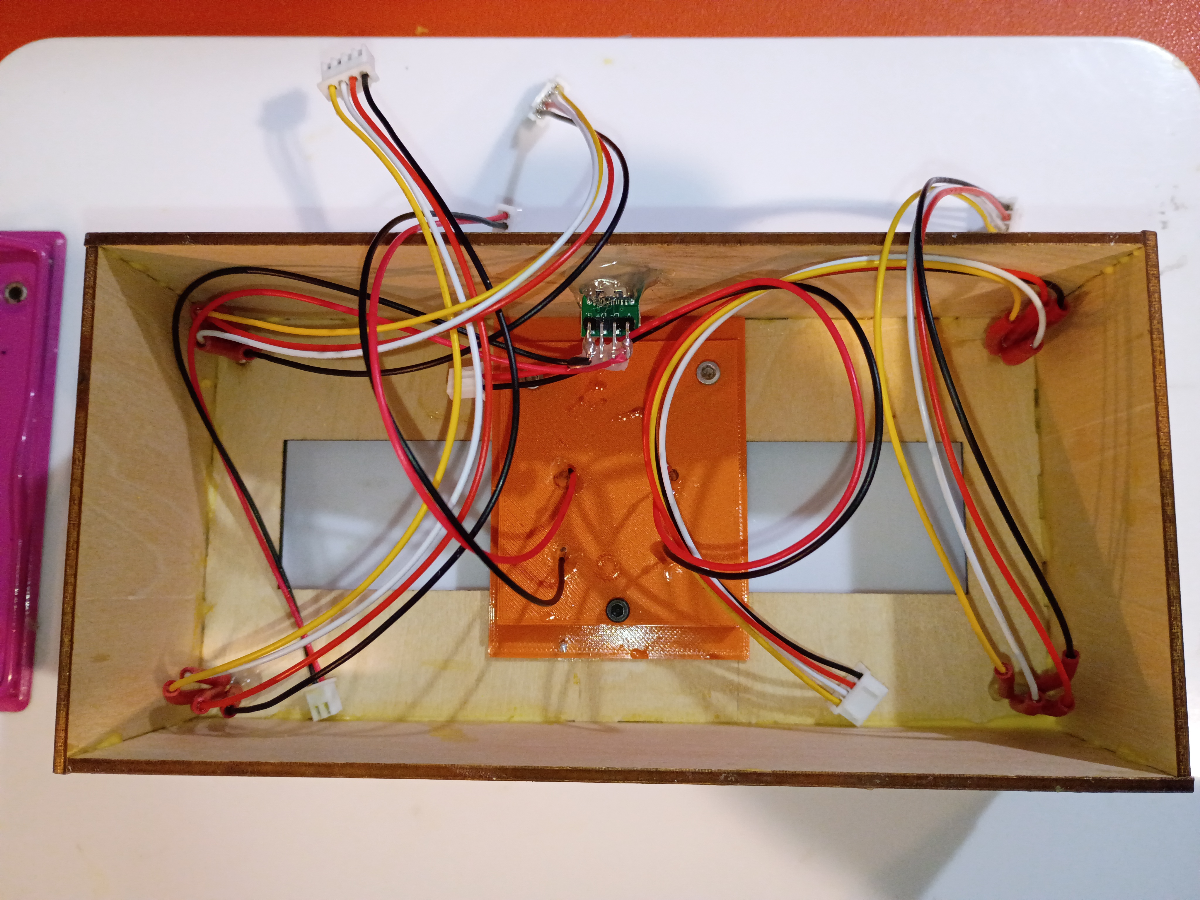
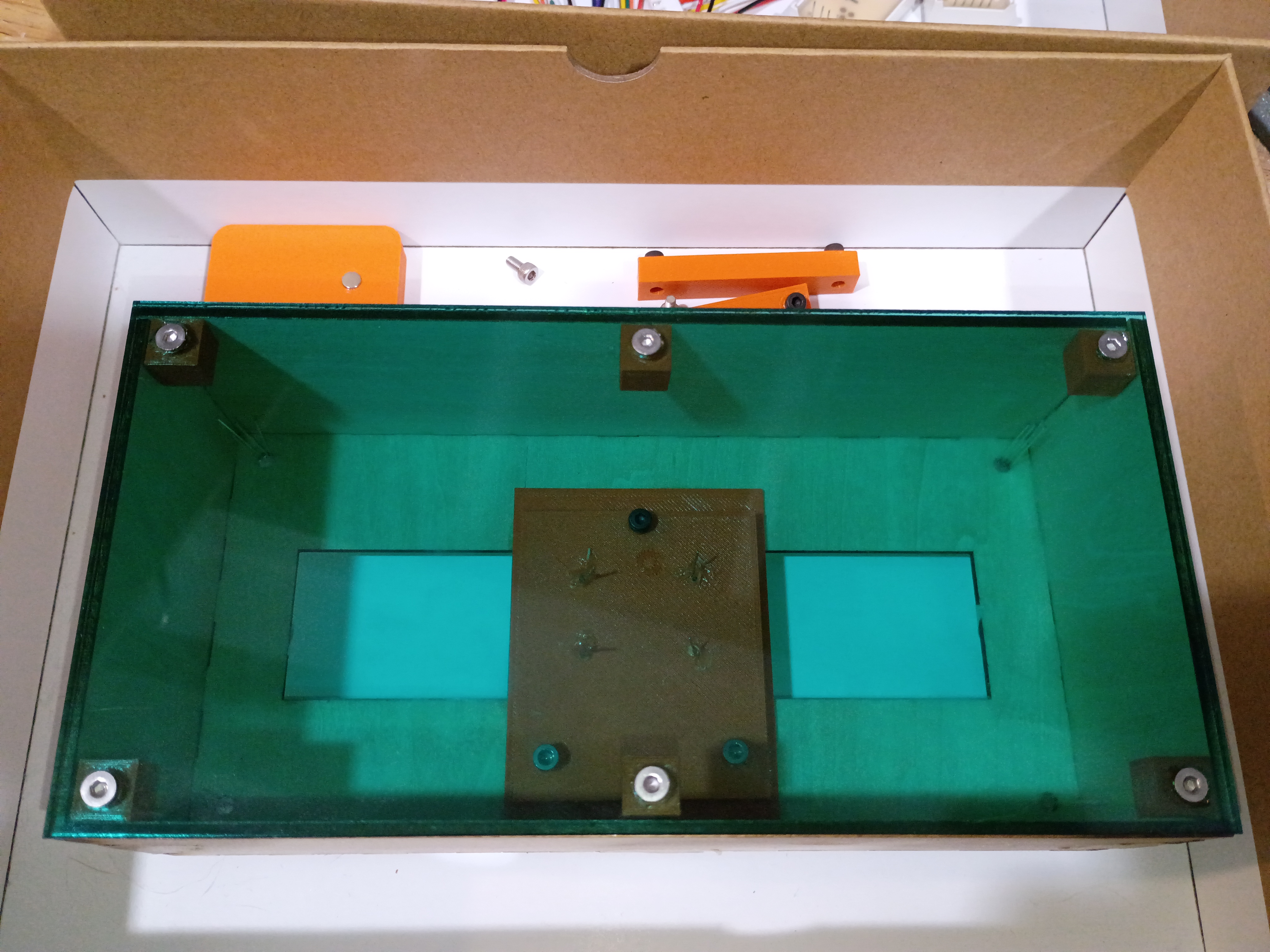
I conducted a preliminary fitment test of most of the electronic components in the box. I determined that getting small custom PCBs produced will drastically simplify the wiring and keep the box contents neat and robust. 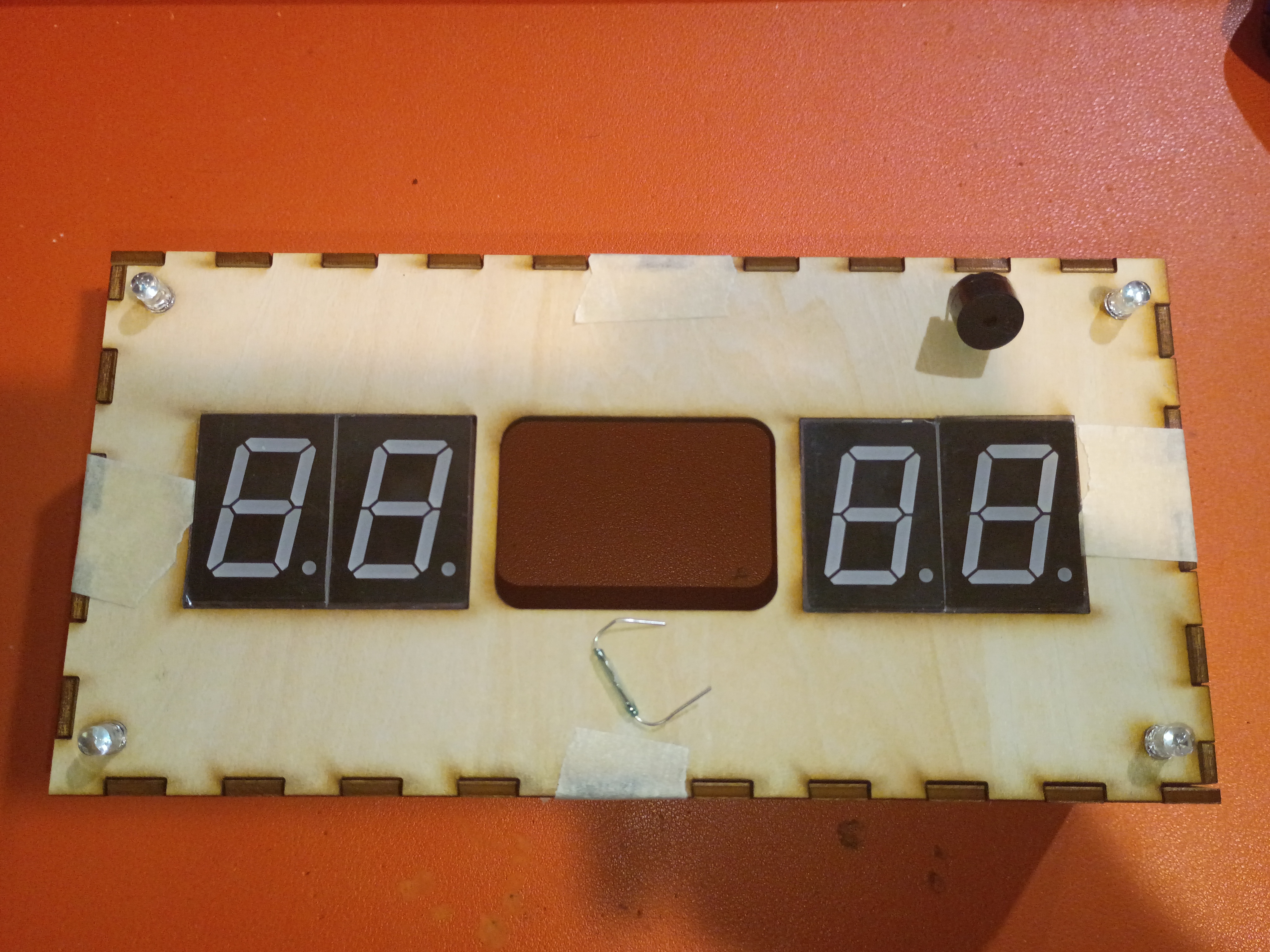
Laser cut around 30 finger-spacers. 20% power 20% current are decent settings for engraving the surface of plywood. Customer was satisfied. 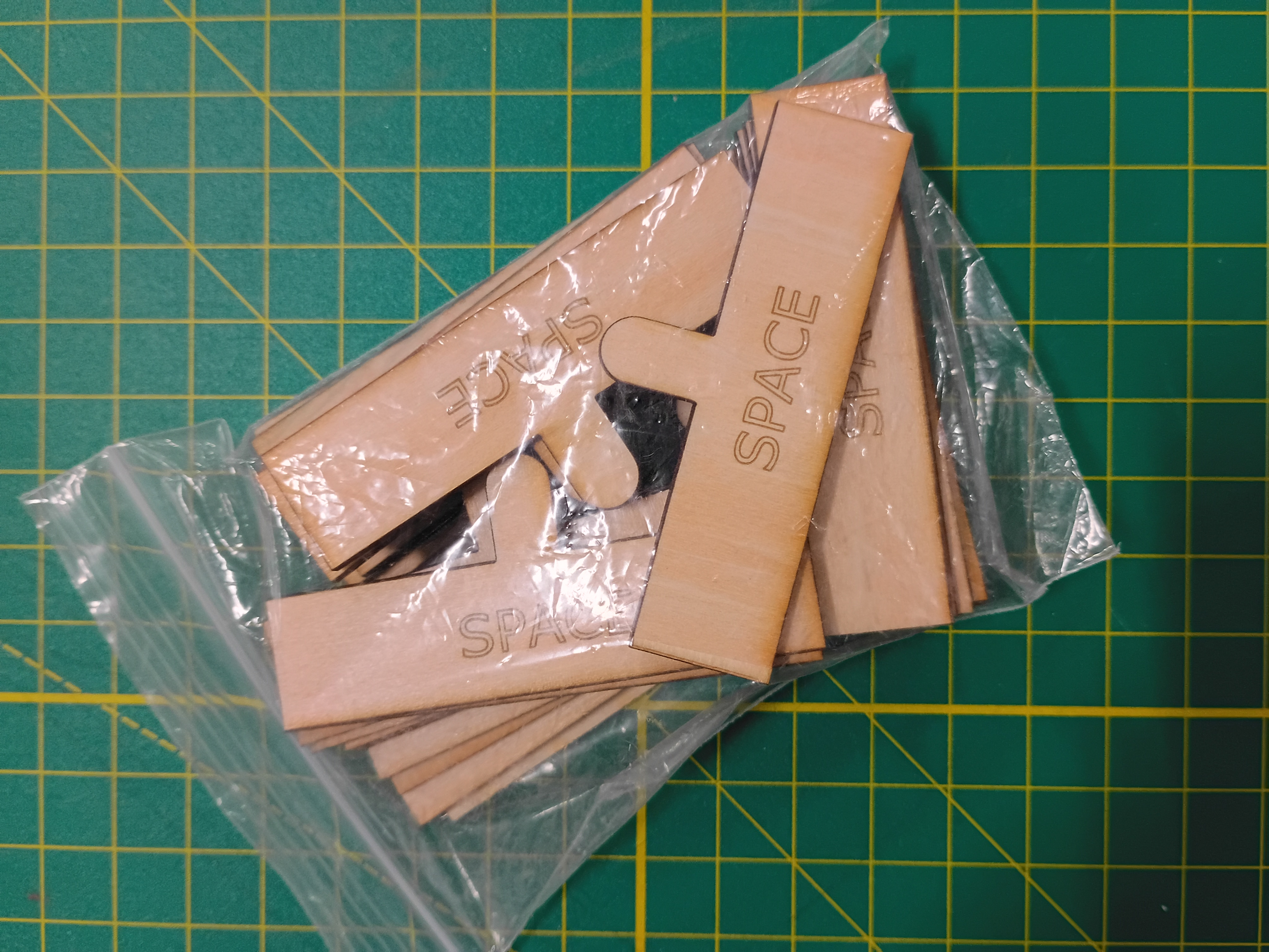
Most of draft box laser cut from 1/8-inch plywood with 3x10mm rectangular jagged edges. 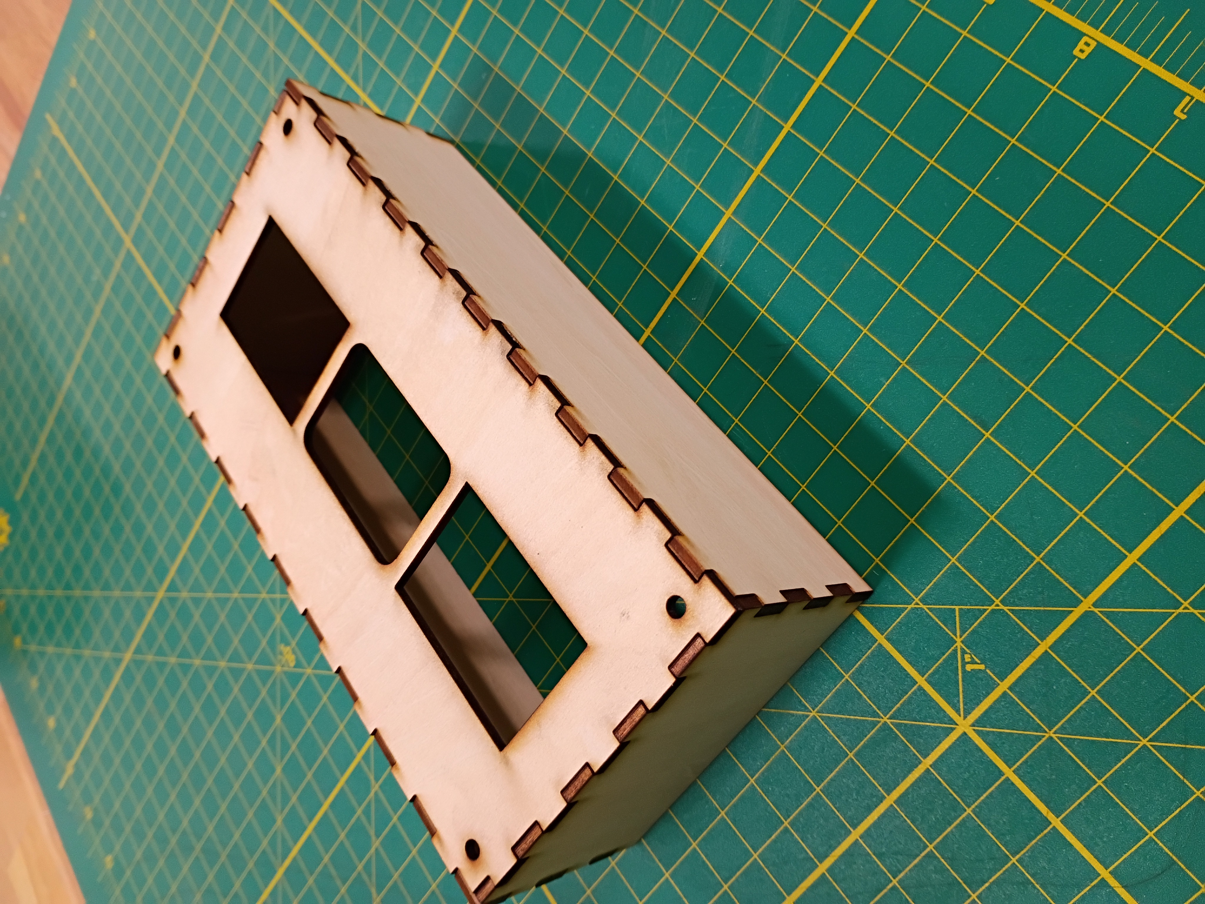
I wrapped up the 3D and laser cut definition for the box sides. 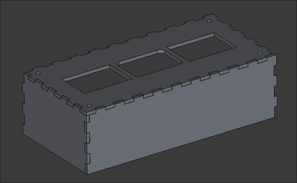
Created an SVG path for a finger-spacer tool to be laser cut. It helps children leave a space between words when they write. 
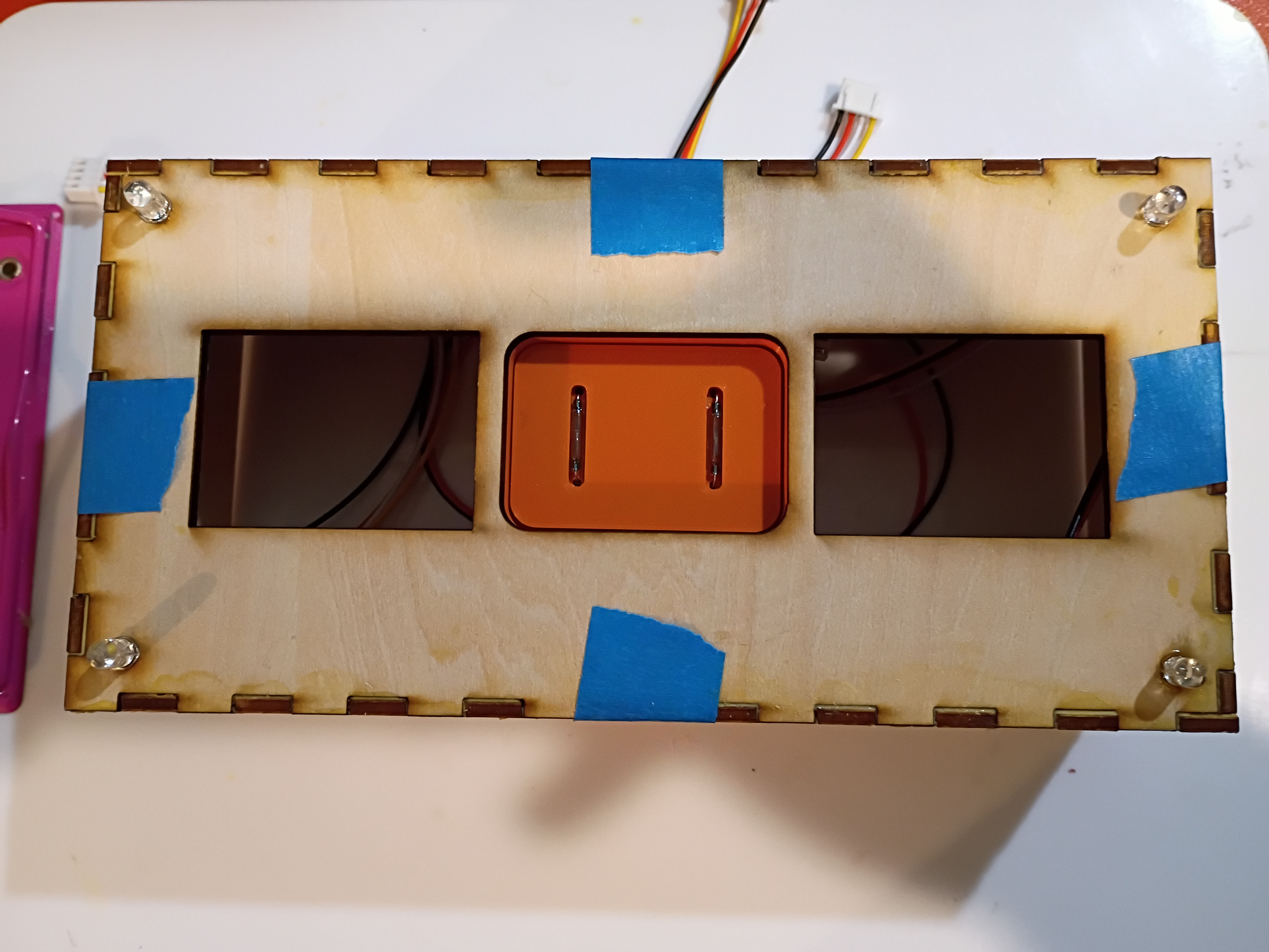
I mocked up a preliminary faceplate SVG to be laser cut. It has holes for the 7-segments, RGB LEDs & central block. 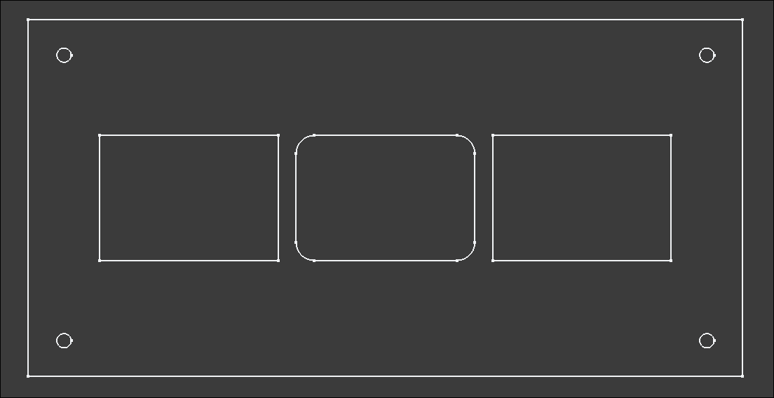
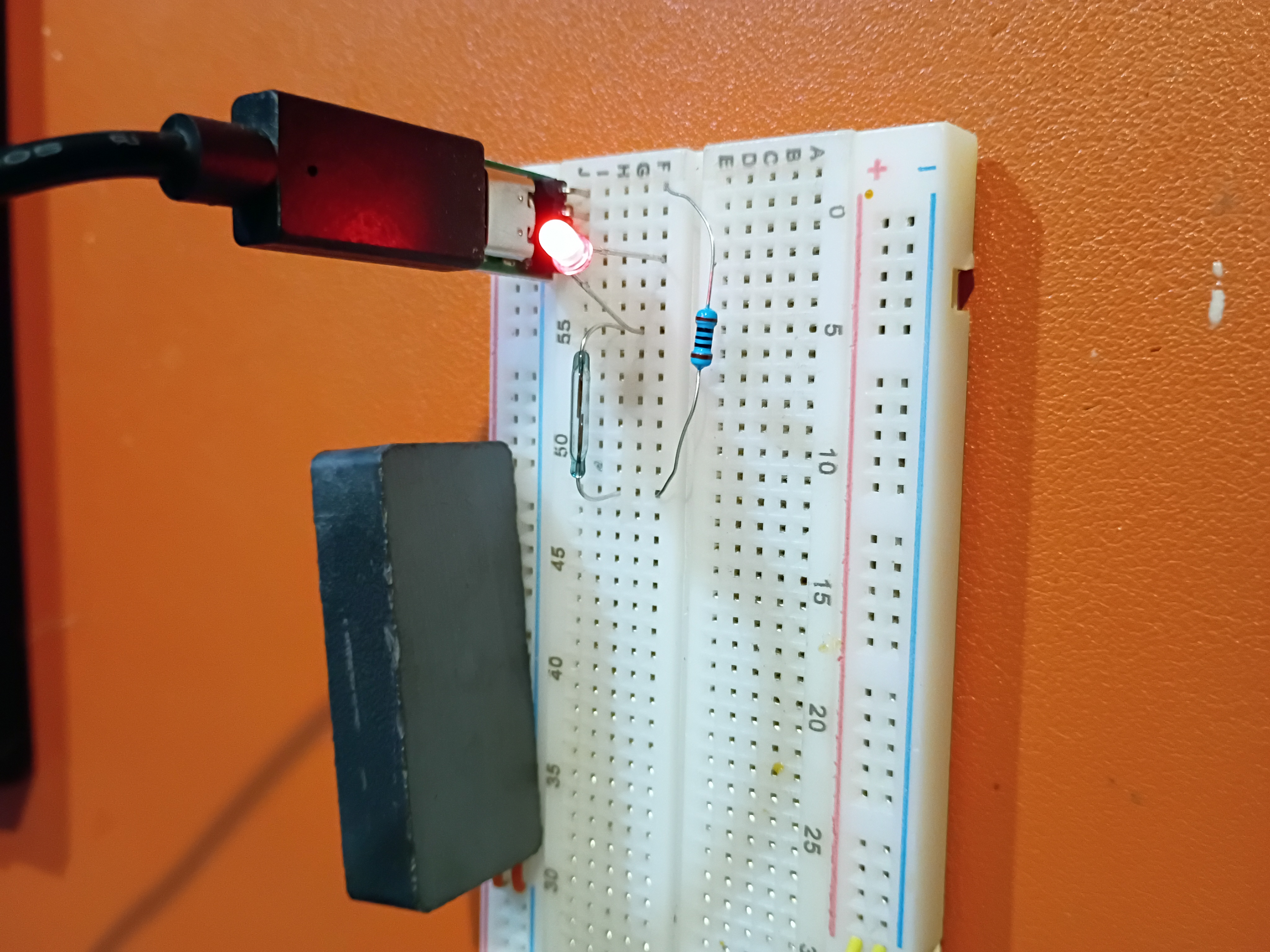
I also tested a USB-C power supply and a Reed switch as an alternative to the Hall effect sensor. It is extremely sensitive.
I updated the GitHub workflow and script to automatically create thumbnail images and added a shorthand for embedding & linking them, among other website formatting improvements.
I adapted the Atmega328P C code to control the 4x separate 7-segment displays.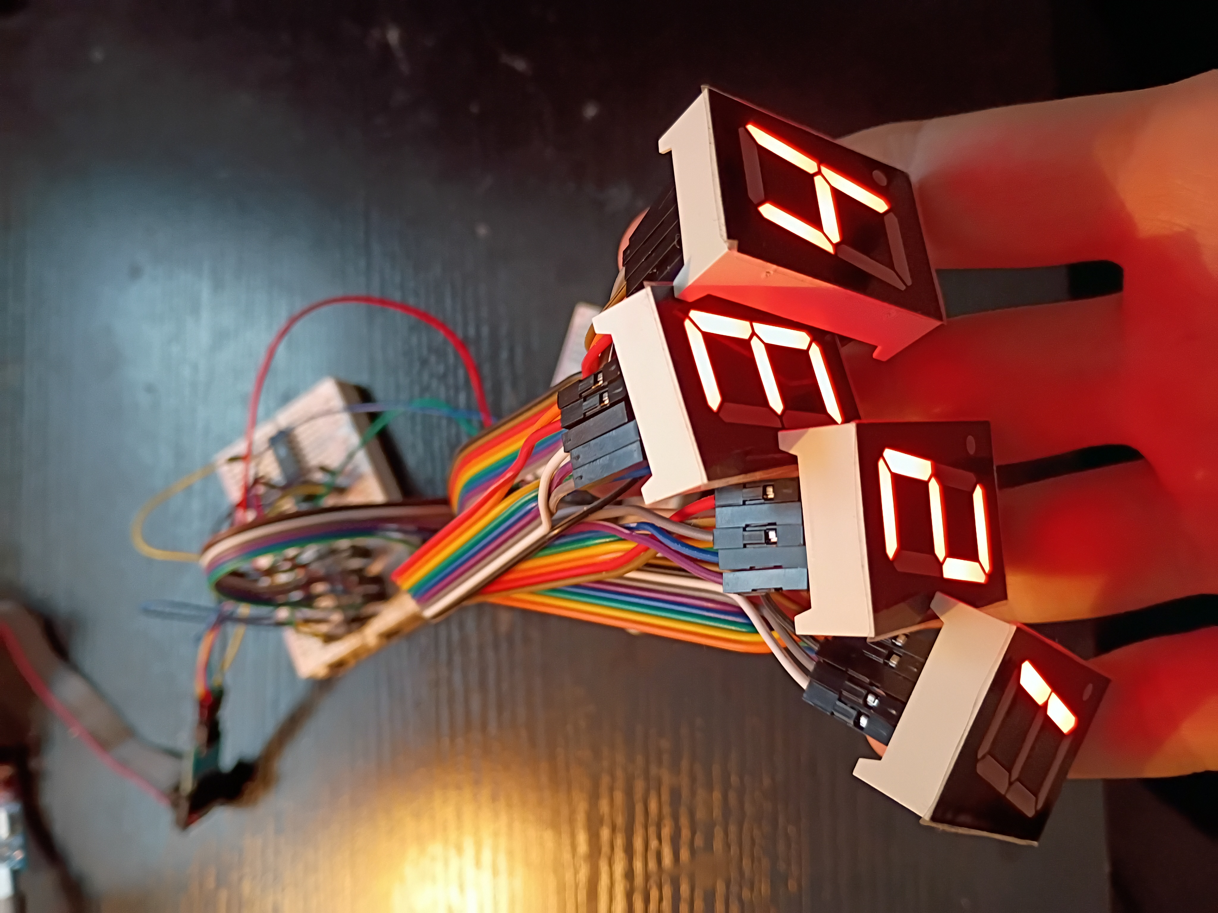
I hooked up 4x 7-segment displays to the MAX7219 IC for testing tomorrow.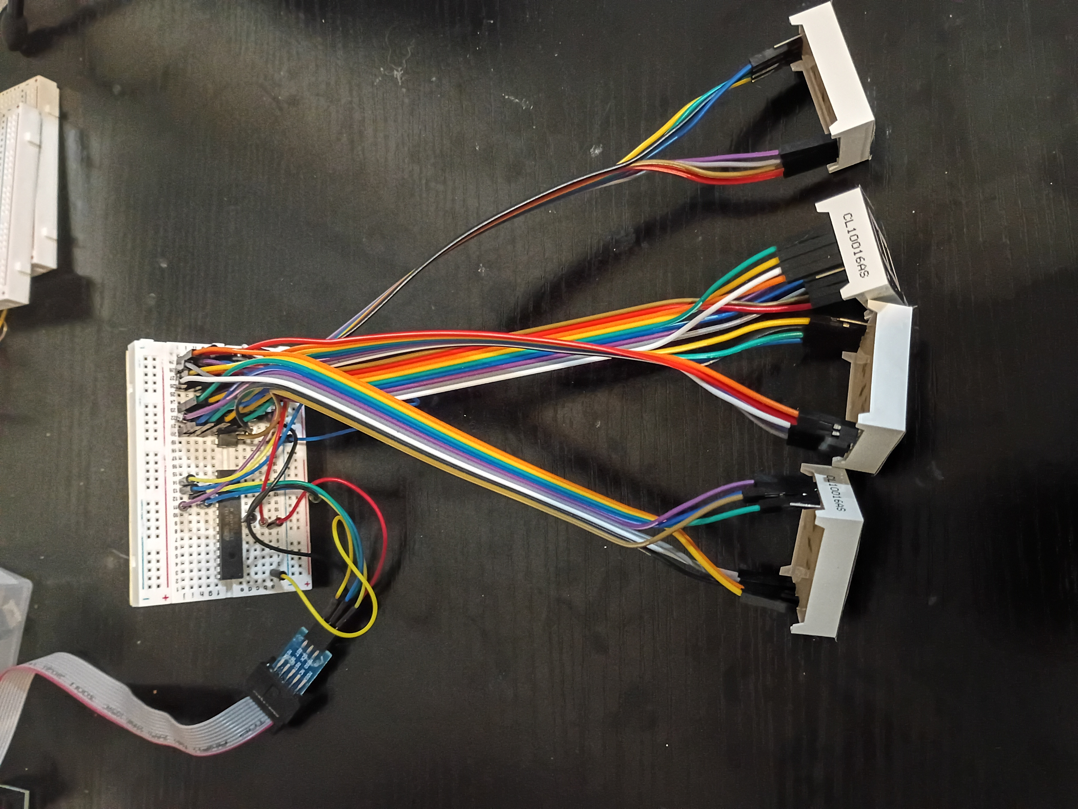
After much debugging (2 days), I realized I had the Rset resistor on the MAX7219 jumping to GND instead of 5V. I thought for sure it was supposed to go to GND. Either way, we have this Atmega328P C code to control a 7-segment display over what is essentially SPI.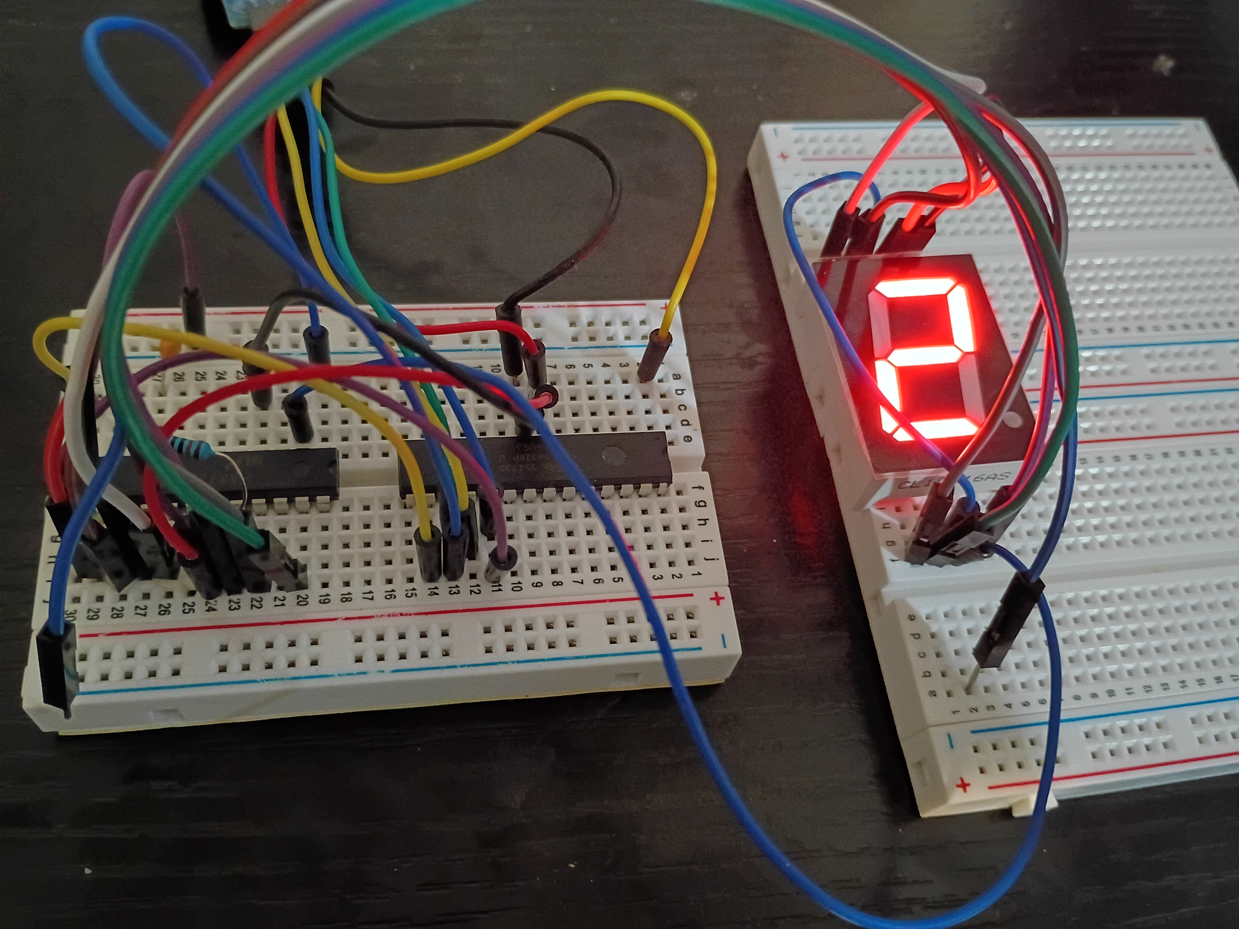
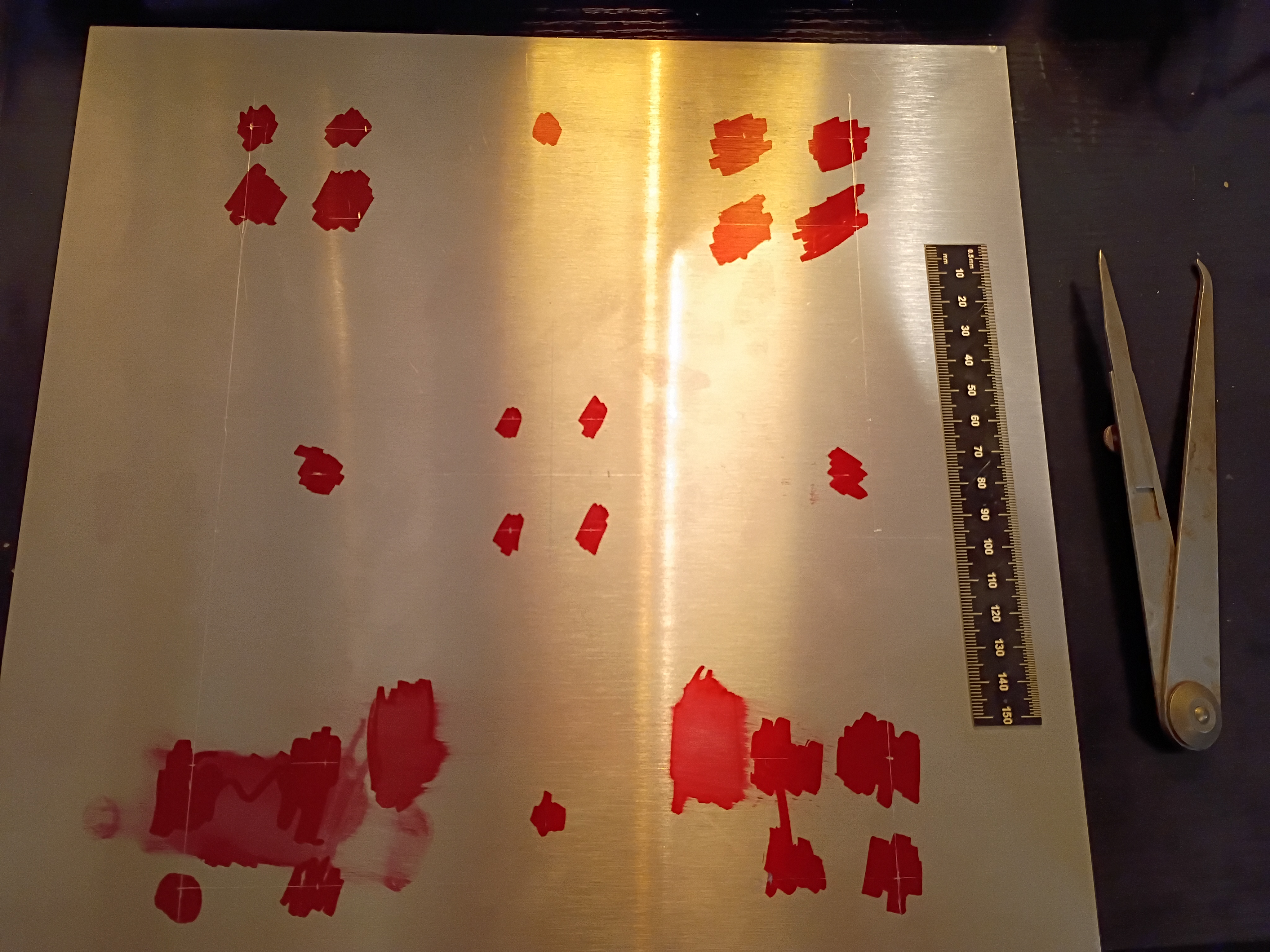
Got some exposure to laser cutting on the Muse3D at work. Made some personal engravings and tested various power setting and cut speeds. At 100% power even 100% speed is enough to cut thru 1/8-inch plywood.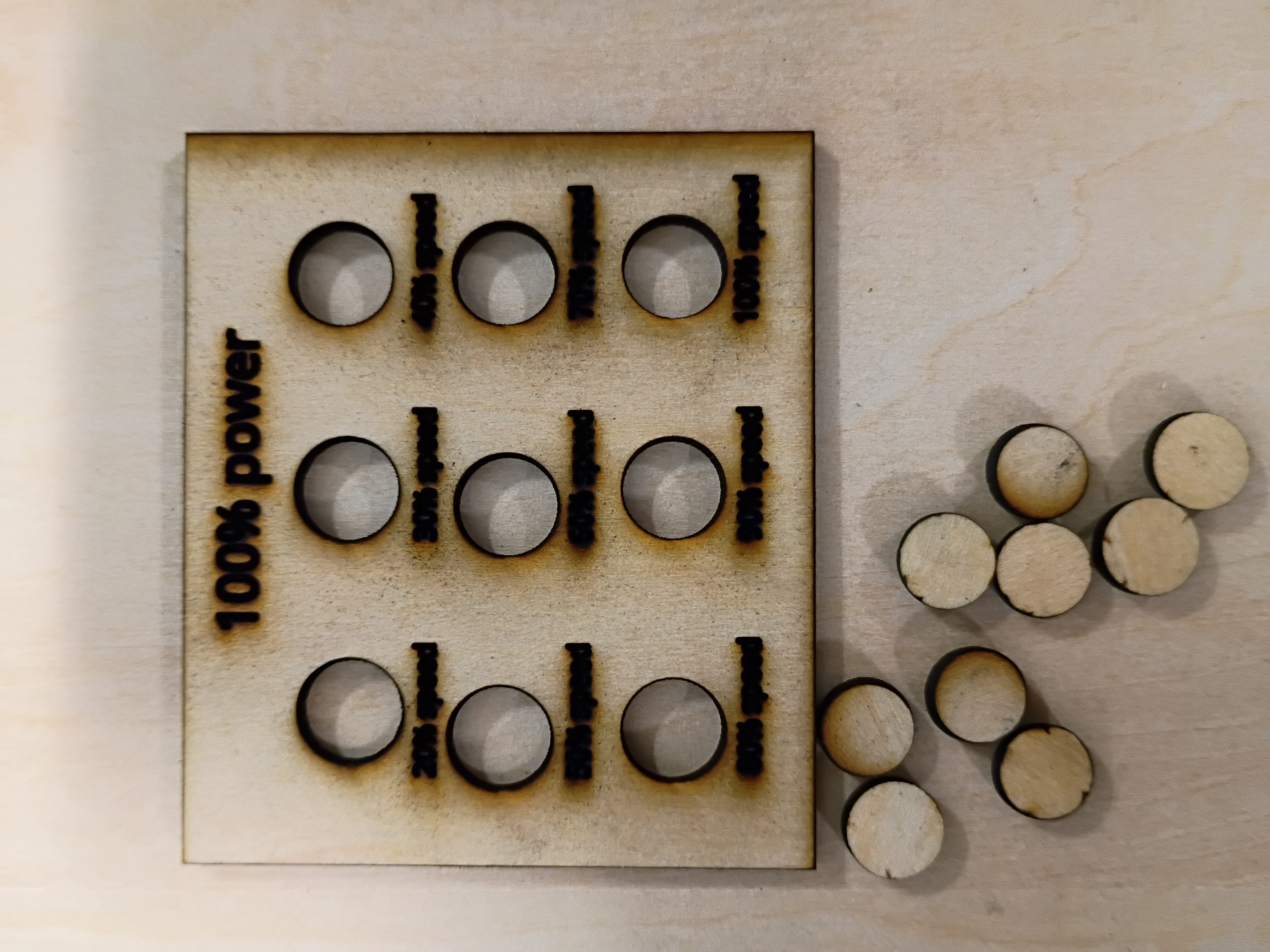
I set up an automated GitHub workflow to generate these journal entry pages automatically and updated the construction script to handle an index page. More to come.
I attempted to implement a circuit to control a 7-segment display using the MAX7219 driver IC, but unfortunately my 7-segment displays are all common-anode, so they are not trivially compatible. While I source common-cathode ones, I tested a basic digit Hall-effect circuit using an LED.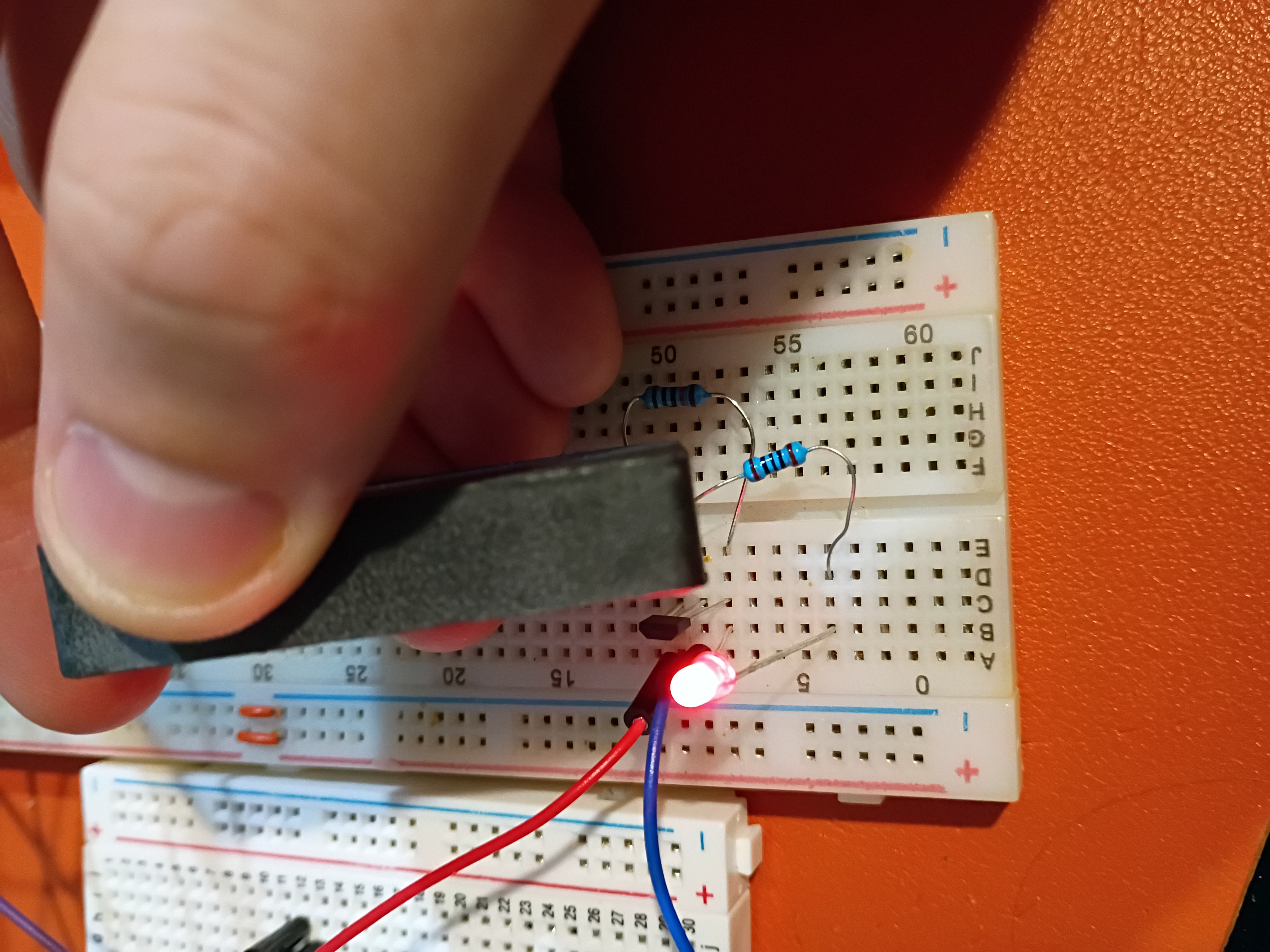
I tested control of an RGB LED with an Atmega328P here.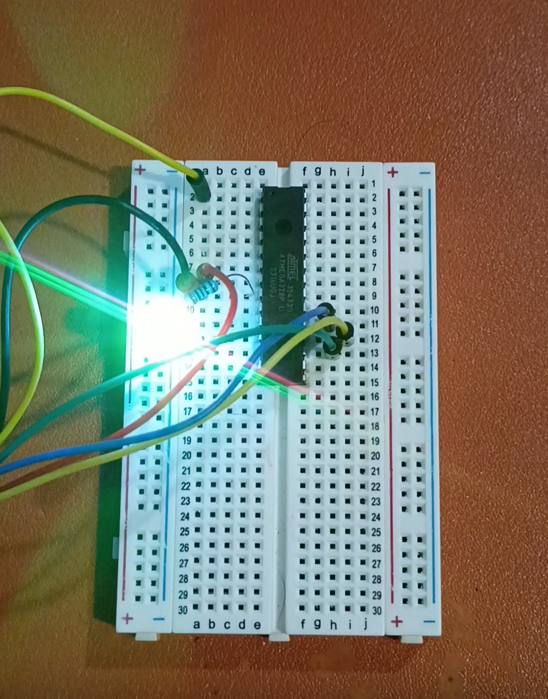
In response to RFP004 - MM1, two candidate 'microcontroller experiences' were proposed in submission xMM1.